Kia Stinger CK: Power Door Locks / Power Door Lock Module
Components and components location
| Components |
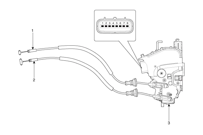
| 1. Door lock/unlock knob cable
2. Door inside handle cable |
3. Door latch assembly |
Repair procedures
| Inspection |
|

Front Door Lock Module Inspection
| 1. |
Remove the front door trim. (Refer to Body - "Front Door Trim") |
| 2. |
Remove the front door module. (Refer to Body - "Front Door Module") |
| 3. |
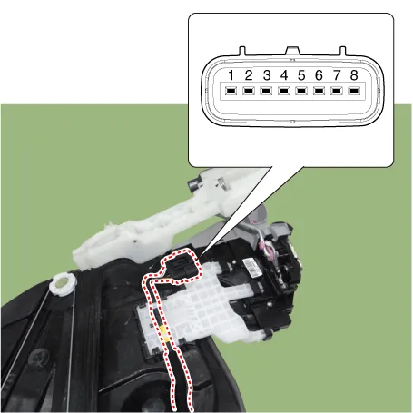
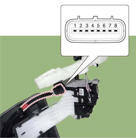
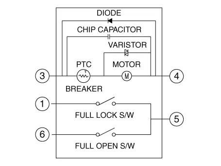
Disconnect the connector from the actuator.
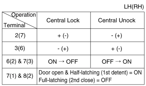
[Central Lock]
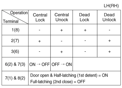
[Dead Lock]
|
||||||||||||||||||||||||||||||||||||||||||||||||||||||||||
| 4. |
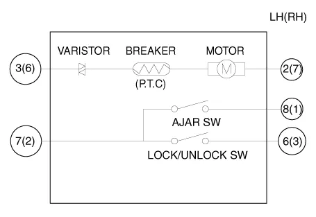
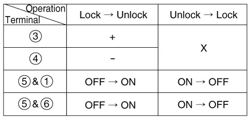
Check actuator operation by connecting power and ground as shown below. To prevent damage to the actuator, apply battery voltage only momentarily. [Central Lock (Without key switch)]
[Dead Lock (Without Key Switch)]
[Dead Lock (With Key Switch)]
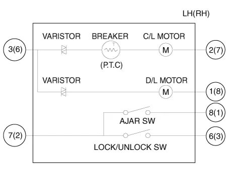
[Central Lock]
[Dead Lock]
|
Rear Door Lock Module Inspection
| 1. |
Remove the rear door trim. (Refer to Body - "Rear Door Trim") |
| 2. |
Remove the rear door module. (Refer to Body - "Rear Door Module") |
| 3. |
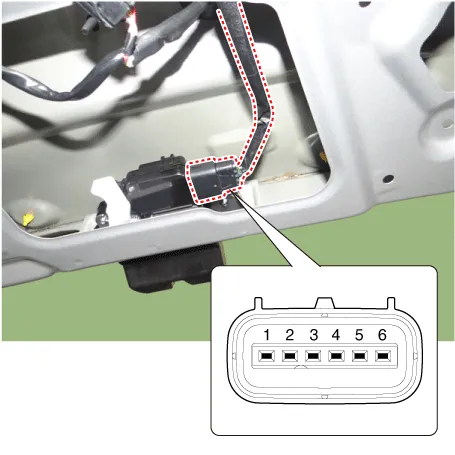
Disconnect the connector from the actuator.
[Central Lock]
[Dead Lock]
|
||||||||||||||||||||||||||||||||||||||||||||||||||||||||||
| 4. |
Check actuator operation by connecting power and ground as shown below. To prevent damage to the actuator, apply battery voltage only momentarily. [Central Lock (Without key switch)]
[Dead Lock (Without Key Switch)]
[Central Lock]
[Dead Lock]
|
Tailgate Lock Module Inspection
| 1. |
Remove the tailgate trim. (Refer to Body - "Tailgate Trim") |
| 2. |
Disconnect the connectors from the actuator.
|
| 3. |
Check actuator operation by connecting power and ground as shown below. To prevent damage to the actuator, apply battery voltage only momentarily.
|
| 4. |
Checking the tailgate of the vehicle power option power refers to the tailgate module. |


Other information:
Kia Stinger (CK) 2018-2023 Service Manual: Emergency Call (eCall) Unit
Components and components location Component The eCall unit for AVN is equipped in AVN head unit. Repair procedures Removal Carry out the Test Mode after: – Replacing the eCall unit – Replacing the Back-up Battery (BUB) – Replacing the eCall speaker and MIC – Replacing the eCall antenna and roof antenna • Be careful not to scratch the cluster fascia panel and related parts.Kia Stinger (CK) 2018-2023 Service Manual: Rear Door Outside Handle
Components and components location Component Location 1. Rear door outside handle Repair procedures Replacement Put on gloves to protect your hands. • Use a plastic panel removal tool to remove interior trim pieces without marring the surface.Categories
- Manuals Home
- Kia Stinger Owners Manual
- Kia Stinger Service Manual
- New on site
- Most important about car
