Kia Stinger CK: Power Windows / Power Window Switch
Components and components location
| Components |
Driver Power Window Switch
Assist Power Window Switch
Rear Power Window Switch
Schematic diagrams
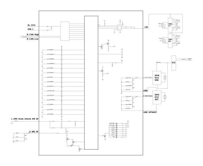
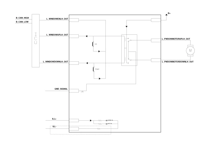
| Circuit Diagram |
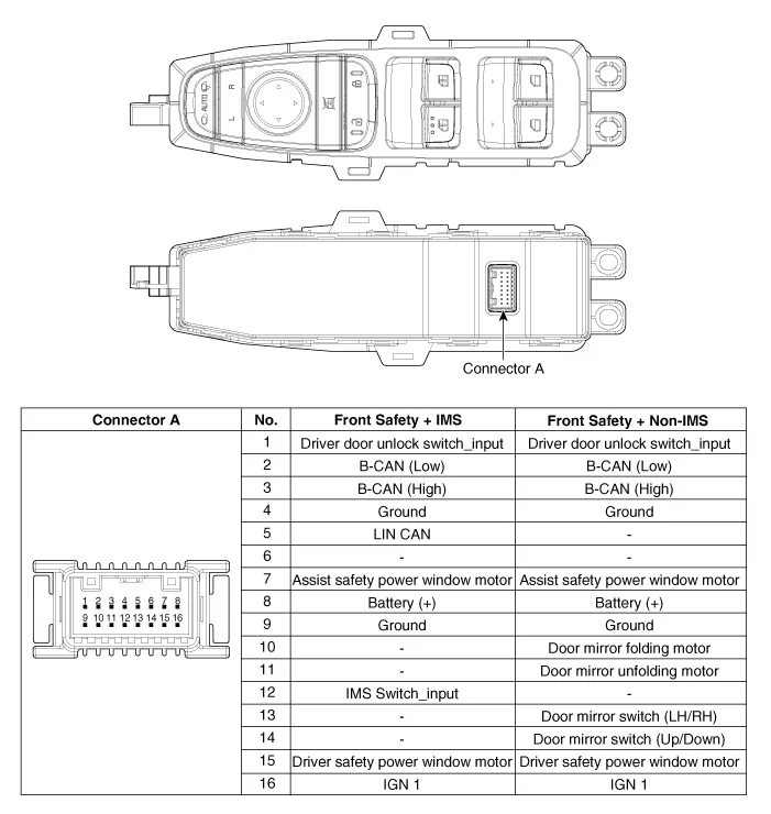
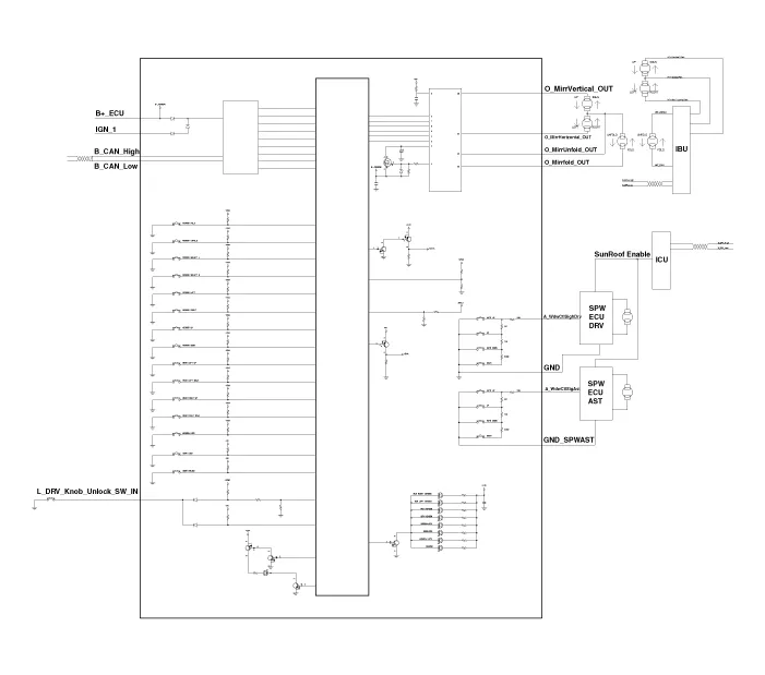
Driver Power Window Switch
| [Front Safety + IMS Type] |
| [Front Safety + Non-IMS Type] |
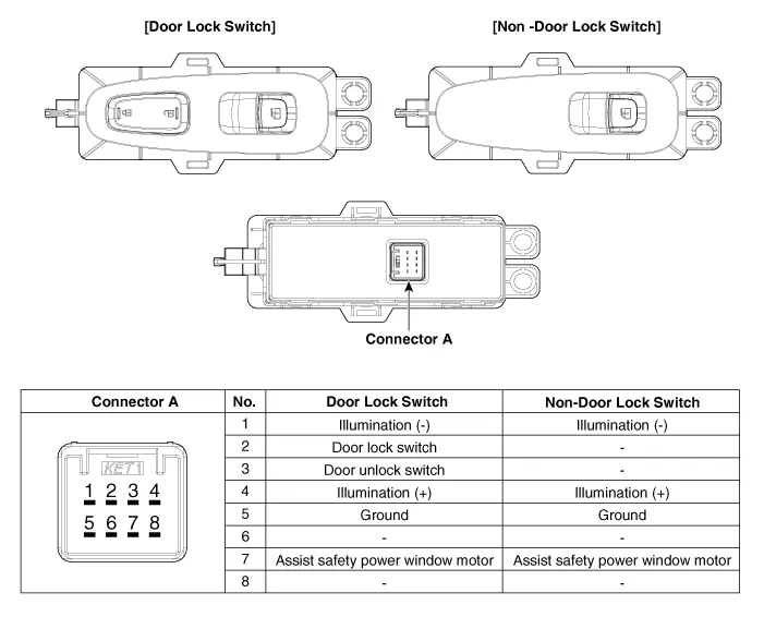
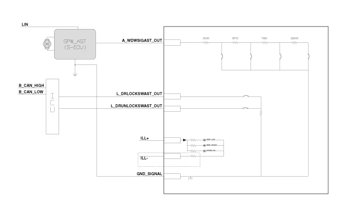
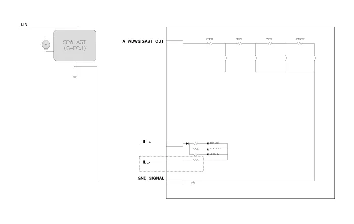
Assist Power Window Switch
| [Door Lock Type] |
| [Non-Door Lock Type] |
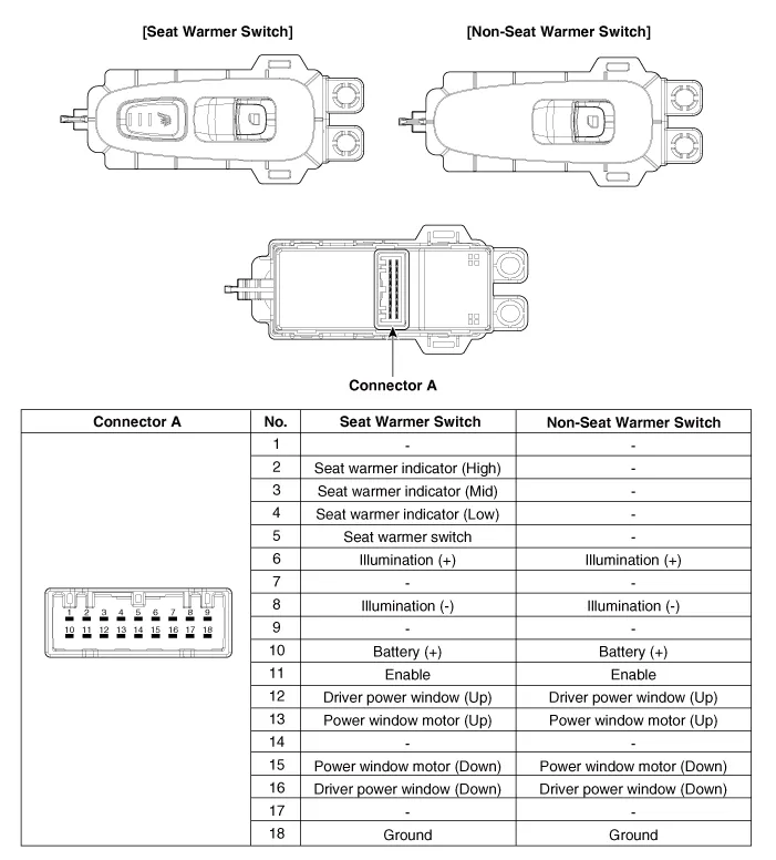
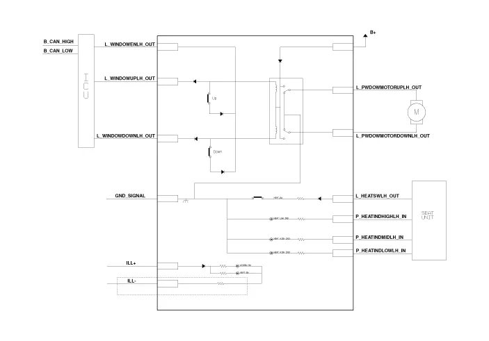
Rear Power Window Switch
| [Seat Warmer Type] |
| [Non-Seat Warmer Type] |
Repair procedures
| Inspection |
Diagnosis With KDS
| 1. |
The body electrical system can be quickly diagnosed for failed parts by using vehicle diagnostic system (KDS). The diagnostic system (KDS) provides the following information.
|
| 2. |
Select the 'Car model' and the system to be checked in order to check the vehicle with the tester. |
| 3. |
Select the 'Driver seat or Assistant seat door module (DDM/ADM)' to check the driver seat or assistant door module (DDM/ADM). |
| 4. |
Select the "Current Data" menu to search the current state of the input/output data. The input/output data for the sensors corresponding to the driver seat or assistant door module(DDM/ADM) can be checked. |
| 5. |
If you will check the power door lock operation forcefully, select "Actuation test". |
| Removal |
Driver Power Window Switch
|

| 1. |
Disconnect the negative (-) battery terminal. |
| 2. |
Remove the driver front door trim. (Refer to Body - "Front Door Trim") |
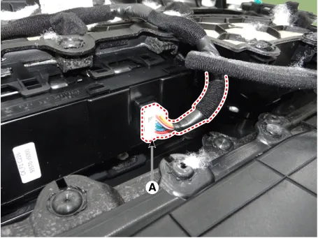
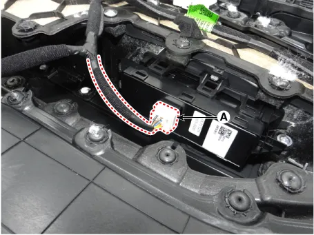
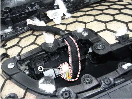
| 3. |
Disconnect the power window switch connector (A).
|
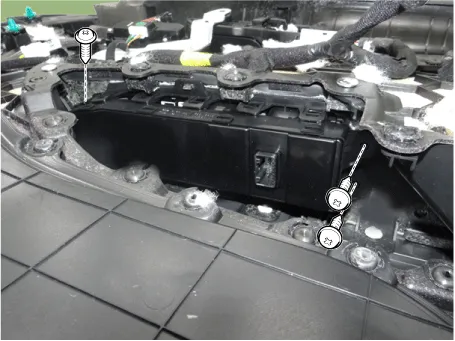
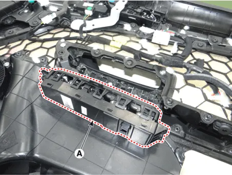
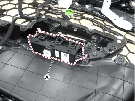
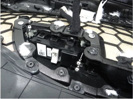
| 4. |
Remove the power window switch (A) after loosening the mounting screws.
|
Assist Power Window Switch
|
| 1. |
Disconnect the negative (-) battery terminal. |
| 2. |
Remove the assist front door trim. (Refer to Body - "Front Door Trim") |
| 3. |
Disconnect the power window switch connector (A).
|
| 4. |
Remove the power window switch (A) after loosening the mounting screws.
|

Rear Power Window Switch
|
| 1. |
Disconnect the negative (-) battery terminal. |
| 2. |
Remove the rear door trim. (Refer to Body - "Rear Door Trim") |
| 3. |
Disconnect the power window switch connector (A).
|
| 4. |
Remove the power window switch (A) after loosening the mounting screws.
|
| Installation |
Driver Power Window Switch
| 1. |
Install the power window switch. |
| 2. |
Connect the power window switch connector. |
| 3. |
Install the driver front door trim after connecting the connector. |
| 4. |
Connect the negative (-) battery terminal. |
Assist Power Window Switch
| 1. |
Install the power window switch. |
| 2. |
Connect the power window switch connector. |
| 3. |
Install the assist front door trim after connecting the connector. |
| 4. |
Connect the negative (-) battery terminal. |
Rear Power Window Switch
| 1. |
Install the power window switch. |
| 2. |
Connect the power window switch connector. |
| 3. |
Install the rear door trim after connecting the connector. |
| 4. |
Connect the negative (-) battery terminal. |


Other information:
Kia Stinger (CK) 2018-2023 Service Manual: Rear Glass Defogger
Components and components location Component Location 1. Integrated body control unit (IBU) 2. Rear glass defogger 3. Rear glass defogger switchKia Stinger (CK) 2018-2023 Service Manual: Parking Brake Assembly
Repair procedures Removal 1. Turn ignition switch OFF and disconnect the negative (-) battery cable. 2. Remove the crash pad lower panel. (Refer to Body - "Crash Pad Lower Panel") 3. Remove the knee airbag. (Refer to Restraint - "Knee airbag (KAB) module") 4.Categories
- Manuals Home
- Kia Stinger Owners Manual
- Kia Stinger Service Manual
- New on site
- Most important about car
