Kia Stinger CK: Power Windows / Power Window Motor
Components and components location
| Components |
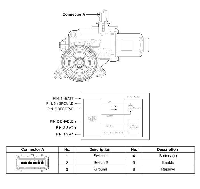
[Safety Window Motor]
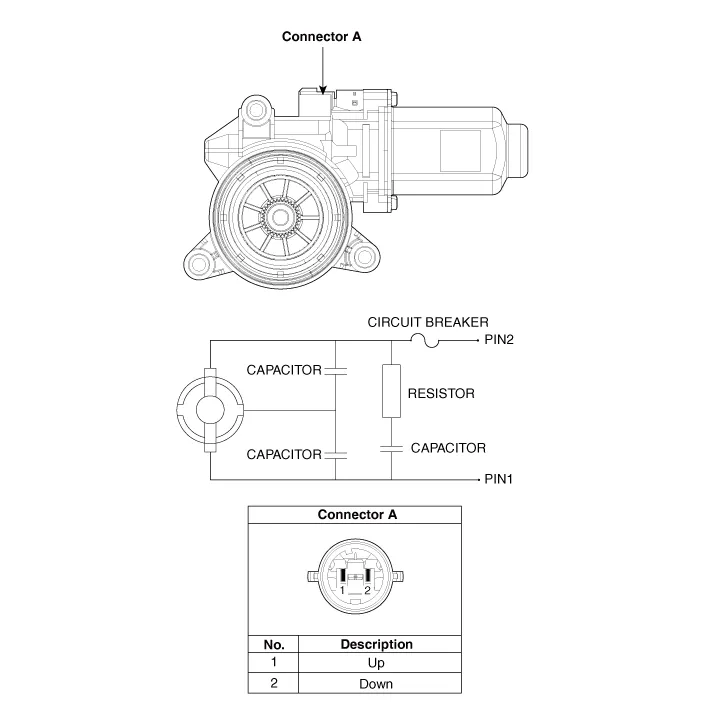
[Standard Window Motor]
Repair procedures
| Removal |
|

Front Power Window Motor
| 1. |
Disconnect the negative (-) battery terminal. |
| 2. |
Remove the front door trim. (Refer to Body - "Front Door Trim") |
| 3. |
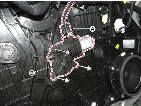
Disconnect the front power window motor connector (A). |
| 4. |
Remove the front power window motor (B) after loosening the mounting bolts.
|
Rear Power Window Motor
| 1. |
Disconnect the negative (-) battery terminal. |
| 2. |
Remove the rear door trim. (Refer to Body - "Rear Door Trim") |
| 3. |
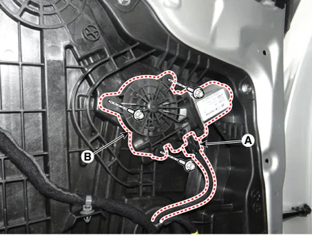
Disconnect the rear power window motor connector (A). |
| 4. |
Remove the rear power window motor (B) after loosening the mounting bolts.
|
| Installation |
Front Power Window Motor
| 1. |
Install the front power window motor. |
| 2. |
Connect the front power window motor connector. |
| 3. |
Install the front door trim. |
| 4. |
Connect the negative (-) battery terminal. |
Rear Power Window Motor
| 1. |
Install the rear power window motor. |
| 2. |
Connect the rear power window motor connector. |
| 3. |
Install the rear door trim. |
| 4. |
Connect the negative (-) battery terminal. |
| Inspection |
[Safety Window Motor]
| Diagnosis With KDS |
| 1. |
In the body electrical system, failure can be quickly diagnosed by using the vehicle diagnostic system (KDS).
|
| 2. |
Select the 'Car model' and the system to be checked in order to check the vehicle with the tester. |
| 3. |
Select the 'Driver seat or Assistant seat door module (DDM/ADM)' to check the driver seat or assistant door module (DDM/ADM). |
| 4. |
Select the "Current Data" menu to search the current state of the input/output data. The input/output data for the sensors corresponding to the driver seat or assistant door module(DDM/ADM) can be checked. |
| 5. |
To check the power window motor operation by force, select "Actuation test". |
[Standard Window Motor]
| 1. |
Disconnect the negative (-) battery terminal. |
| 2. |
Remove the rear door trim. (Refer to Body - "Rear Door Trim") |
| 3. |
Disconnect the motor connector (A) from the motor.
|
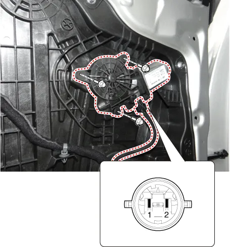
| 4. |
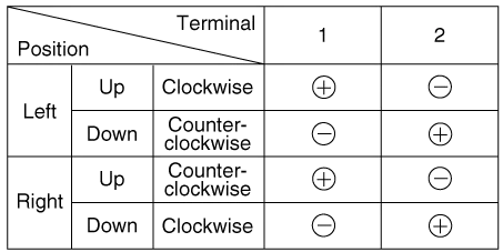
Connect the motor terminals directly to battery voltage (12V) and check that the motor operates smoothly. Next, reverse the polarity and check that the motor operates smoothly in the reverse direction. If the operation is abnormal, replace the motor.
|


Other information:
Kia Stinger (CK) 2018-2023 Service Manual: Rear Stabilizer Bar
Repair procedures Removal 1. Remove wheel nuts, wheel and tire (A) from hub. Tightening torque: 107.9 - 127.5 N·m (11.0 - 13.0 kgf·m, 79.6 - 94.0 lb·ft) Be careful not to damage the wheel bolts when removing the wheel and tire (A).Kia Stinger (CK) 2018-2023 Service Manual: Lower Anchors and Tether for Children (LATCH) System
The LATCH system holds a child restraint during driving and in an accident. This system is designed to make installation of the child restraint easier and reduce the possibility of improperly installing your child restraint. The LATCH system uses anchors in the vehicle and attachments on the child restraint. The LATCH system eliminates the need to use seat belts to secure the child restraint to the rear seats.Categories
- Manuals Home
- Kia Stinger Owners Manual
- Kia Stinger Service Manual
- New on site
- Most important about car
