Kia Stinger CK: Brake System / Vacuum Pump
Components and components location
| Components |
| 3.3 T-GDI LAMBDA II |
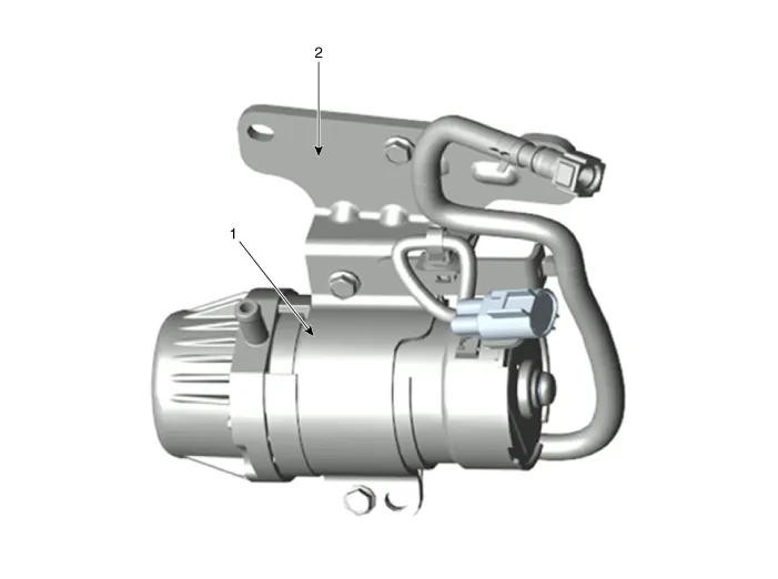
| 1. Vacuum pump |
2. Vacuum pump bracket |
| 2.0 T-GDI THETA II |
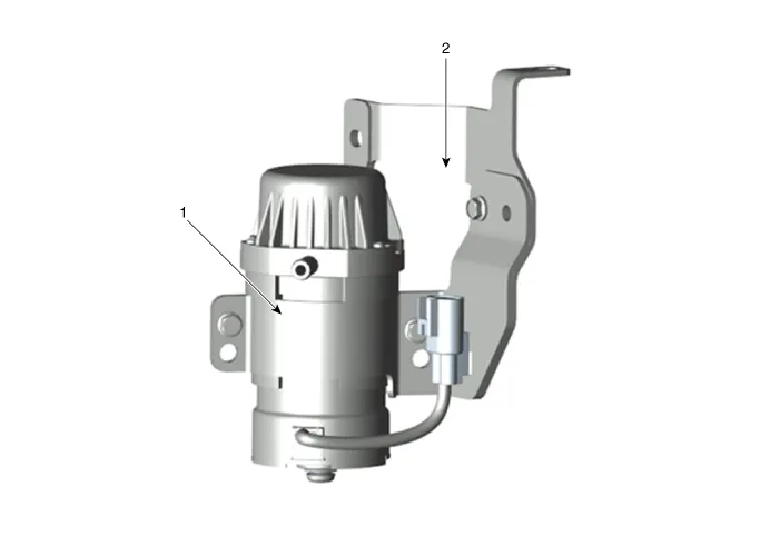
| 1. Vacuum pump |
2. Vacuum pump bracket |
Repair procedures
| Removal |
[3.3 T-GDI LAMBDA II]
| 1. |
Turn ignition switch OFF and disconnect the negative (-) battery cable. |
| 2. |
Remove the engine room under cover. (Refer to Engine Mechanical System - "Engine room under cover") |
| 3. |
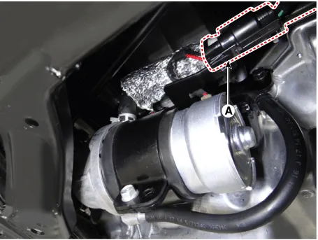
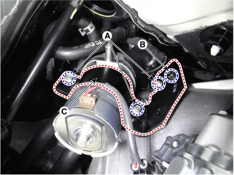
Disconnect the vacuum pump connector (A).
|
| 4. |
Disconnect the vacuum pump hose (A) from the vacuum pump.
|

| 5. |
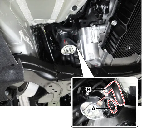
Loosen the vacuum pump bolts (B) and then remove the vacuum pump (A).
|

| 6. |
Install in the reverse order of removal. |
[2.0 T-GDI THETA II]
| 1. |
Turn ignition switch OFF and disconnect the negative (-) battery cable. |
| 2. |
Remove the engine room under cover. (Refer to Engine Mechanical System - "Engine room under cover") |
| 3. |
Disconnect the vacuum pump connector (A) and vacuum pump hose (B).
|
| 4. |
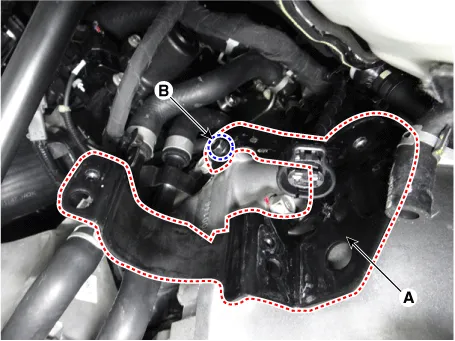
Loosen the vacuum pump bracket bolts (A),(B) and then remove the vacuum pump bracket.
|
| 5. |
Remove the vacuum pump (A).
|

| 6. |
Loosen the vacuum pump bracket bolt (B) and then remove the vacuum pump bracket (A).
|
| 7. |
Install in the reverse order of removal. |


Other information:
Kia Stinger (CK) 2018-2023 Service Manual: Basic Service Symbols
General information Basic Service Symbols There are five primary symbols used to complement illustrations. These symbols indicate the part to apply such materials during service. Symbol Meaning Do not reuse the part. Replace a new one. Apply engine oil or transmission oil to the part.Kia Stinger (CK) 2018-2023 Service Manual: Low Pressure Fuel Pump
Repair procedures Inspection [Fuel sender] 1. Switch "OFF" the ignition and disconnect the negative (-) battery terminal. 2. Remove the fuel pump assembly. 3. Using an ohmmeter, measure the resistance between terminals 1 and 2 of sender connector (A) at each float level.Categories
- Manuals Home
- Kia Stinger Owners Manual
- Kia Stinger Service Manual
- New on site
- Most important about car
