Kia Stinger CK: Brake System / Master Cylinder
Components and components location
| Components |
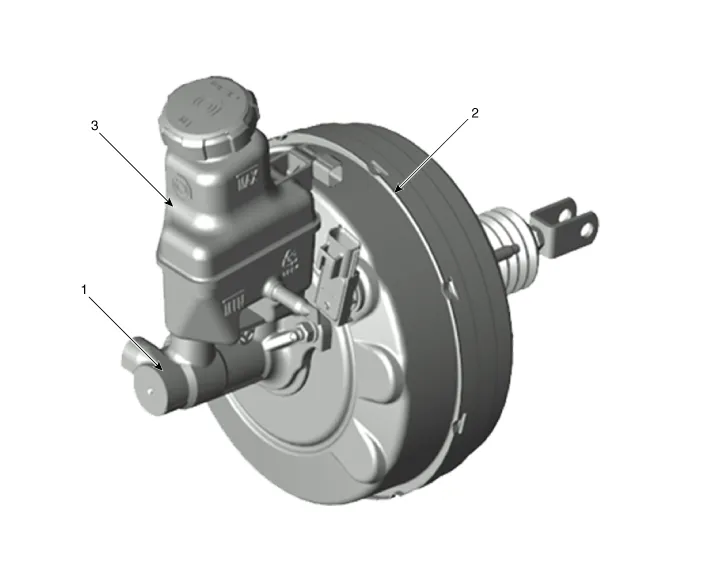
| 1. Master cylinder 2. Brake booster |
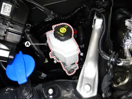
3. Brake reservoir |
Repair procedures
| Removal |
[LHD]
| 1. |
Turn ignition switch OFF and disconnect the negative (-) battery cable. |
| 2. |
Remove the brake fluid from the master cylinder reservoir with a syringe.
|

| 3. |
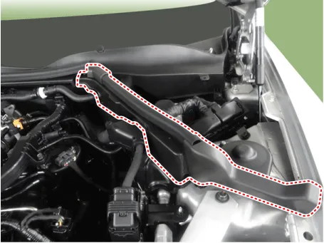
Remove the hood sealing cover.
|
| 4. |
Remove the engine control module (ECM). D 2.2 R VGT (Refer to Engine Control /Fuel System - "Engine Control Module (ECM)") D 2.2 R VGT (Enhanced Euro 6) (Refer to Engine Control /Fuel System - "Engine Control Module (ECM)") G 2.0 T-GDI (Refer to Engine Control /Fuel System - "Engine Control Module (ECM)") G 3.3 T-GDI (Refer to Engine Control /Fuel System - "Engine Control Module (ECM)") |
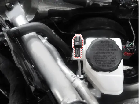
| 5. |
Disconnect the brake fluid level sensor connector.
|
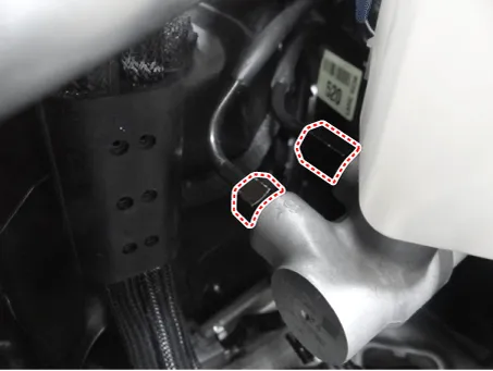
| 6. |
Loosen the master cylinder flare nuts.
|
| 7. |
Remove the master cylinder from the brake booster after loosening the mounting nuts.
|
[RHD]
| 1. |
Turn ignition switch OFF and disconnect the negative (-) battery cable. |
| 2. |
Remove the brake fluid from the master cylinder reservoir with a syringe.
|
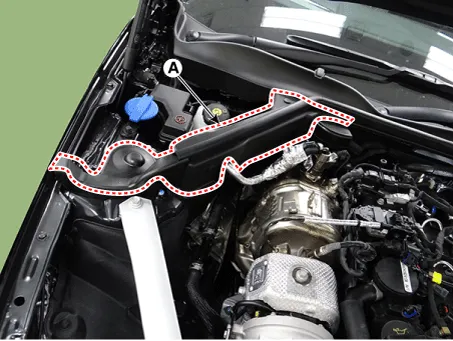
| 3. |
Remove the RH hood sealing cover (A).
|
| 4. |
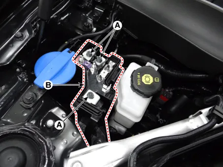
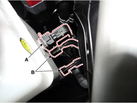
Disconnect the wirings (A) from the joint junction block. |
| 5. |
Detach the joint junction block (B).
|
| 6. |
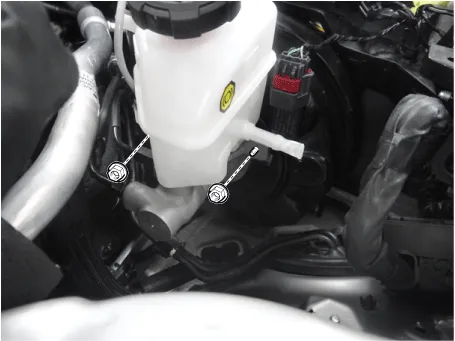
Disconnect the brake fluid level sensor connector (A). |
| 7. |
Loosen the master cylinder flare nuts (B).
|
| 8. |
Remove the master cylinder (A) from the brake booster after loosening the mounting nuts.
|
| Installation |
| 1. |
Install in the reverse order of removal. |
| 2. |
After installation, bleed the brake system. (Refer to Brake system - "Brake Bleeding Procedures") |


Other information:
Kia Stinger (CK) 2018-2023 Service Manual: Brake Pedal
Components and components location Components 1. Brake lamp switch 2. Brake pedal Repair procedures Removal [LHD] 1. Turn ignition switch OFF and disconnect the negative (-) battery cable. 2. Remove the crash pad lower panel. (Refer to Body - "Crash Pad Lower Panel") 3.Kia Stinger (CK) 2018-2023 Service Manual: Front Propeller Shaft
Repair procedures Removal 1. Raise the vehicle, and make sure it is securely supported. 2. Remove the engine room side cover. D 2.2 R VGT (Refer to Engine Mechanical System - "Engine Room Under cover") G 2.0 T-GDI THETA II (Refer to Engine Mechanical System - "Engine Room Under cover") G 3.Categories
- Manuals Home
- Kia Stinger Owners Manual
- Kia Stinger Service Manual
- New on site
- Most important about car
