Kia Stinger CK: Brake System / Brake Pedal
Components and components location
| Components |
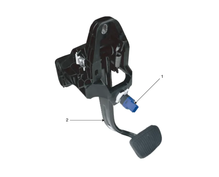
| 1. Brake lamp switch |
2. Brake pedal |
Repair procedures
| Removal |
[LHD]
| 1. |
Turn ignition switch OFF and disconnect the negative (-) battery cable. |
| 2. |
Remove the crash pad lower panel. (Refer to Body - "Crash Pad Lower Panel") |
| 3. |
Remove the knee airbag. (Refer to Restraint - "Knee airbag (KAB) module") |
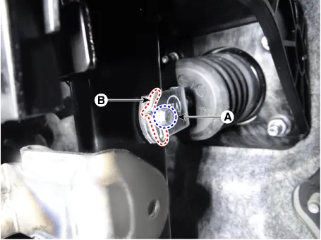
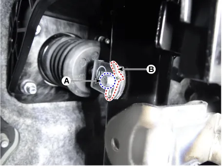
| 4. |
Remove the snap pin (A) and clevis pin (B).
|
| 5. |
Remove the stop lamp switch connector. (Refer to Brake System - "Stop lmap switch") |
| 6. |
Loosen the brake pedal stopper nuts and then remove the brake pedal stopper.
|

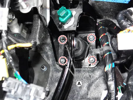
| 7. |
Remove the brake booster mounting nuts (A).
|

| 8. |
Remove the brake pedal upper bolt and then remove the brake pedal assembly.
|

[RHD]
| 1. |
Turn ignition switch OFF and disconnect the negative (-) battery cable. |
| 2. |
Remove the crash pad lower panel. (Refer to Body - "Crash Pad Lower Panel") |
| 3. |
Remove the knee airbag. (Refer to Restraint - "Knee airbag (KAB) module") |
| 4. |
Remove the integrated central control unit (ICU). (Refer to Body Electrical System - "Relay Box (Passenger Compartment)") |
| 5. |
Remove the snap pin (A) and clevis pin (B).
|
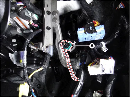
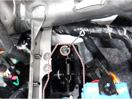
| 6. |
Disconnect the stop lamp switch connector (A).
|
| 7. |
Loosen the brake pedal stopper nuts and then remove the brake pedal stopper (A).
|

| 8. |
Remove the brake booster mounting nuts (A).
|
| 9. |
Loosen the brake pedal upper bolt (A).
|
| 10. |
Remove the brake pedal assembly (A).
|

| Inspection |
| 1. |
Check the bushing for wear. |
| 2. |
Check the brake pedal for bending or twisting. |
| 3. |
Check the brake pedal return spring for damage. |
| 4. |
Check the stop lamp switch. (Refer to Brake System - "Stop Lamp Switch") |
| Installation |
| 1. |
Install in the reverse order of removal. |


Other information:
Kia Stinger (CK) 2018-2023 Service Manual: ECS-G Sensor
Repair procedures Removal [Body G Sensor] Front 1. Turn ignition switch OFF and disconnect the negative (-) battery cable. 2. Remove wheel nuts, wheel and tire (A) from hub. Tightening torque: 107.9 - 127.5 N·m (11.0 - 13.0 kgf·m, 79.6 - 94.0 lb·ft) Be careful not to damage the wheel bolts when removing the wheel and tire (A).Kia Stinger (CK) 2018-2023 Service Manual: Ambient Temperature Sensor
Description and operation Description Located in front of the condenser, the ambient temperature sensor detects the ambient air temperature. It is a negative type thermistor; resistance will increase with lower temperature, and decrease with higher temperature. The sensor output will be used for discharging temperature control, temperature regulation door control, blower motor level control, mix mode control and in-car humidity control.Categories
- Manuals Home
- Kia Stinger Owners Manual
- Kia Stinger Service Manual
- New on site
- Most important about car
