Kia Stinger CK: Brake System / Front Disc Brake
Components and components location
| Components |
| [Standard] |
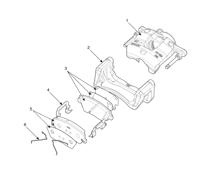
| 1. Caliper housing 2. Brake member 3. Brake pad assembly [IN] |
4. Retainer 5. Brake pad assembly [OUT] 6. Brake pad return spring |
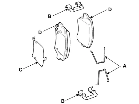
| [Brembo] |
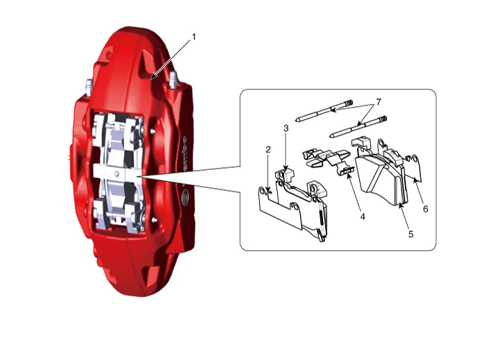
| 1. Caliper housing 2. Brake pad cover 3. Brake pad 4. Retraction spring |
5. Brake pad 6. Brake pad cover 7. Guide pin |
Repair procedures
| Removal |
[Standard]
| 1. |
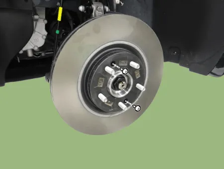
Remove wheel nuts, front wheel and tire (A) from front hub.
|


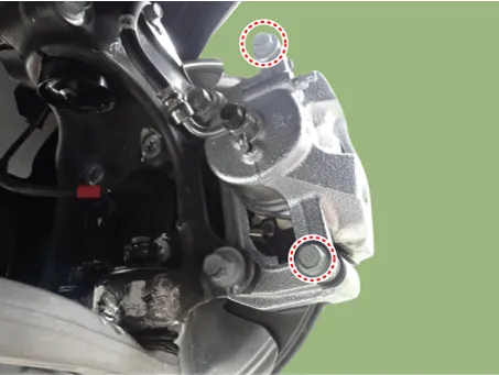
| 2. |
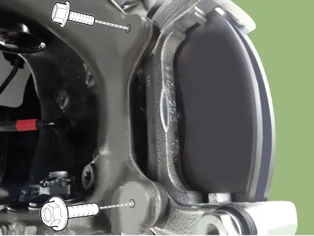
Loosen the brake caliper guide bolts and then remove the brake caliper.
|
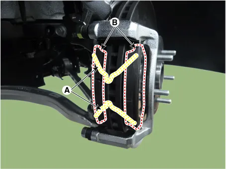
| 3. |
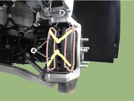
Remove the return spring (A), brake pad (B).
|
| 4. |
Loosen the brake member assembly bolts and then remove the brake member assembly.
|
| 5. |
Loosen the brake disc screw and then remove the brake disc.
|
| 6. |
Install in the reverse order of removal. |
[Brembo]
| 1. |
Remove wheel nuts, front wheel and tire (A) from front hub.
|
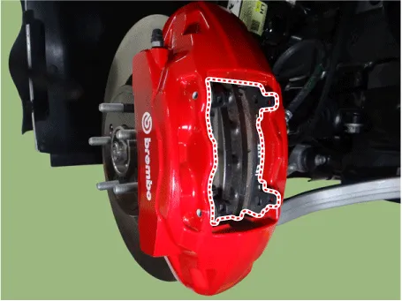
| 2. |
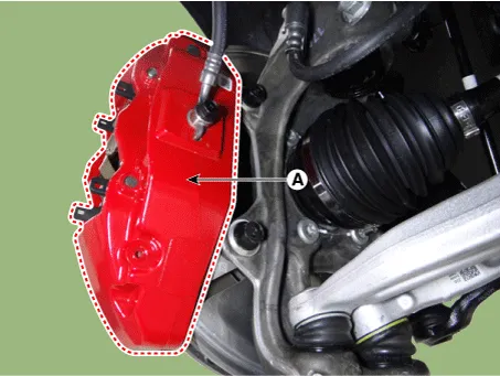
Remove the brake caliper (A).
|
| 3. |
Loosen the brake disc screw and then remove the brake disc.
|
| 4. |
Install in the reverse order of removal. |
| Replacement |
| [Standard] |
Brake pad
| 1. |
Remove wheel nuts, front wheel and tire (A) from front hub.
|
| 2. |
Loosen the guide rod bolt and then pivot the caliper body up out of the way.
|

| 3. |
Remove the return spring (A), brake pad (B).
|
| 4. |
Install in the reverse order of removal. |
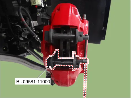
| 5. |
Use the SST (09581-11000) when installing the brake caliper assembly.
|

| 6. |
After installation, bleed the brake system. (Refer to Brake system - "Brake Bleeding Procedures") |
| [Brembo] |
Brake pad
| 1. |
Remove wheel nuts, front wheel and tire (A) from front hub.
|
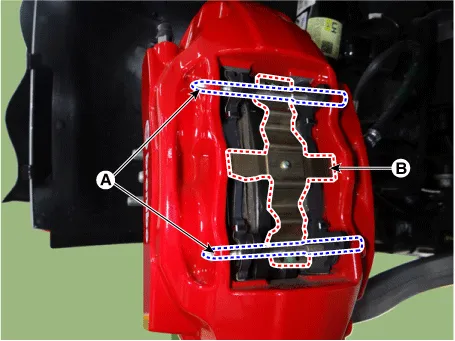
| 2. |
Push the guide pin (A) and then remove the retraction spring (B).
|
| 3. |
Remove the brake pad.
|
| 4. |
Install in the reverse order of removal. |
| 5. |
Use the SST (09581-11000) when installing the brake caliper assembly.
|
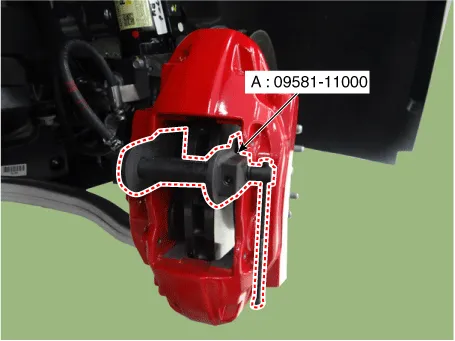
| 6. |
Use the SST (09581-11000) when installing the brake caliper assembly.
|
| 7. |
After installation, bleed the brake system. (Refer to Brake system - "Brake Bleeding Procedures") |
| Inspection |
Front brake disc thickness check
| 1. |
Check the brake pads for wear and fade. |
| 2. |
Check the brake disc for damage and cracks. |
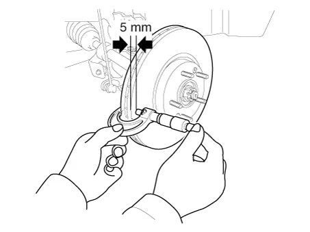
| 3. |
Remove all rust and contamination from the surface, and measure the disc thickness at 8 points, at least, at the same distance (5mm) apart from the brake disc outer circle.
|
| 4. |
If wear exceeds the limit, replace the discs and pad assembly left and right of the vehicle. |
Front Brake Pad Check
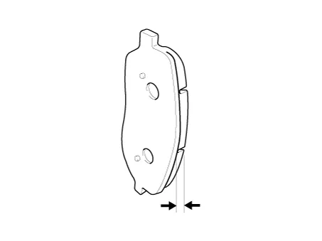
| 1. |
Check the pad wear. Measure the pad thickness and replace it, if it is less than the specified value.
|
| 2. |
Check that grease is applied to sliding contact points and check the pad and backing metal for damage. |
Front brake disc runout check
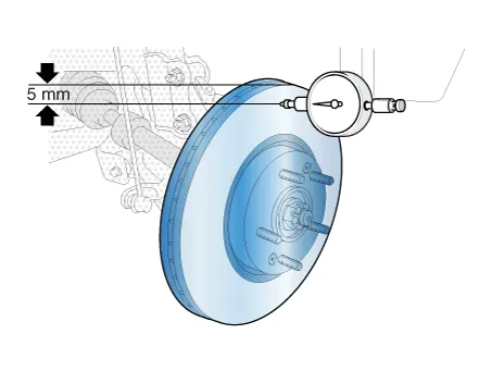
| 1. |
Place a dial gauge about 5mm (0.2 in.) from the outer circumference of the brake disc, and measure the runout of the disc.
|
| 2. |
If the runout of the brake disc exceeds the limit specification, replace the disc, and then measure the runout again. |
| 3. |
If the runout does not exceed the limit specification, install the brake disc after turning it 180° and then check the brake disc again for runout. |
| 4. |
If the runout cannot be corrected by changing the position of the brake disc, replace the brake disc. |


Other information:
Kia Stinger (CK) 2018-2023 Service Manual: Oil Pressure Switch
Repair procedures Removal 1. Disconnect the battery negative terminal. 2. Remove the alternator. (Refer to Engine Electrical System - "Alternator") 3. Disconnect the oil pressure switch connector (A) and then remove the oil pressure switch (B). Tightening torque : 7.Repair procedures Replacement • Special grease must be applied to the driveshaft joint. Do not substitute with another type of grease. • The boot band should be replaced with a new one. 1.Categories
- Manuals Home
- Kia Stinger Owners Manual
- Kia Stinger Service Manual
- New on site
- Most important about car
