Kia Stinger CK: Brake System / Rear Disc Brake
Components and components location
| Components |
| [Standard] |
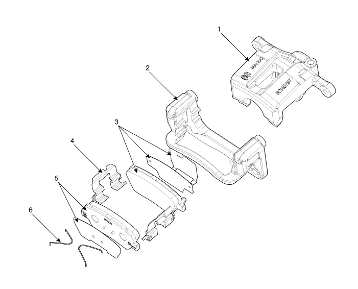
| 1. Caliper housing 2. Brake member 3. Brake pad assembly [IN] |
4. Retainer 5. Brake pad assembly [OUT] 6. Brake pad return spring |
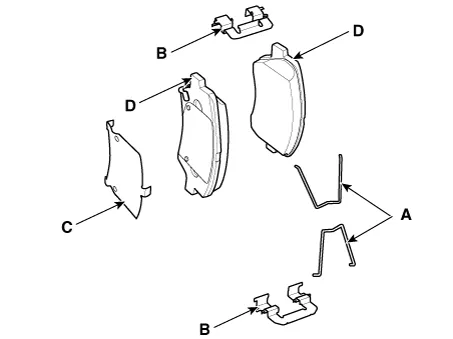
| [Brembo] |
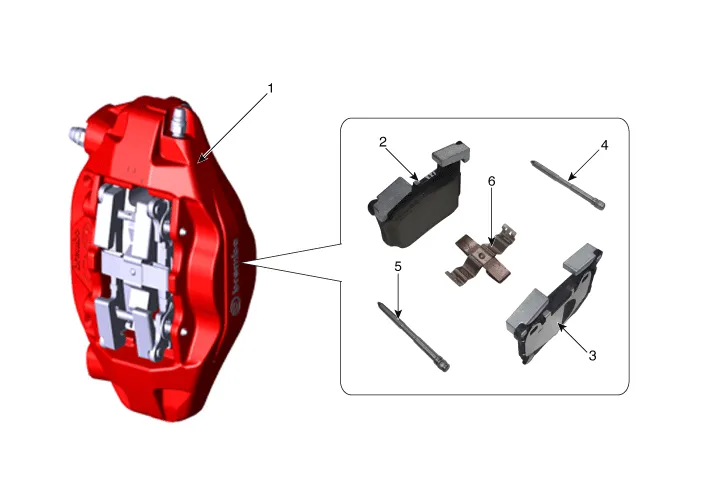
| 1. Caliper housing 2. Brake pad 3. Brake pad |
4. Pin 5. Pin 6. Pad spring |
Repair procedures
| Removal |
[Standard]
| 1. |
Remove wheel nuts, wheel and tire (A) from hub.
|


| 2. |
Loosen the brake caliper guide bolts and then remove the brake caliper.
|
| 3. |
Remove the return spring (A), brake pad (B).
|
| 4. |
Loosen the brake member assembly bolts and then remove the brake member assembly.
|

| 5. |
Loosen the brake disc screw and then remove the brake disc.
|
| 6. |
Install in the reverse order of removal. |
[Brembo]
| 1. |
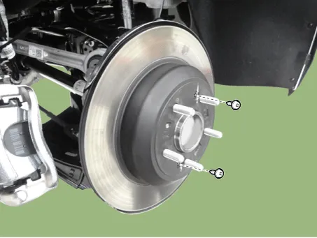
Remove wheel nuts, wheel and tire (A) from hub.
|
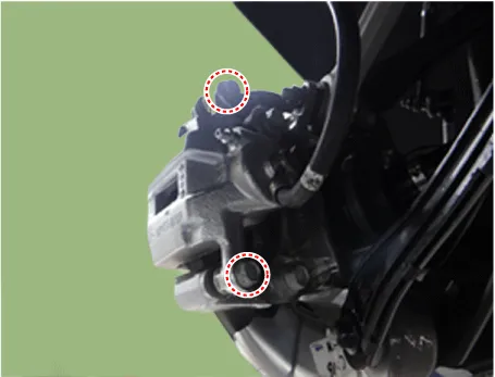
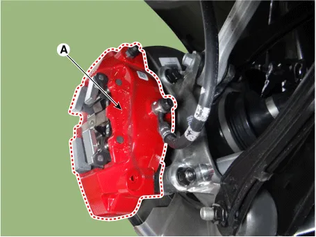
| 2. |
Remove the brake caliper (A).
|
| 3. |
Loosen the brake disc screw and then remove the brake disc.
|
| 4. |
Install in the reverse order of removal. |
| Replacement |
| [Standard] |
Brake pad
| 1. |
Remove wheel nuts, wheel and tire (A) from hub.
|
| 2. |
Loosen the guide rod bolt and then pivot the caliper body down out of the way.
|
| 3. |
Remove the return spring (A), brake pad (B).
|
| 4. |
Install in the reverse order of removal. |
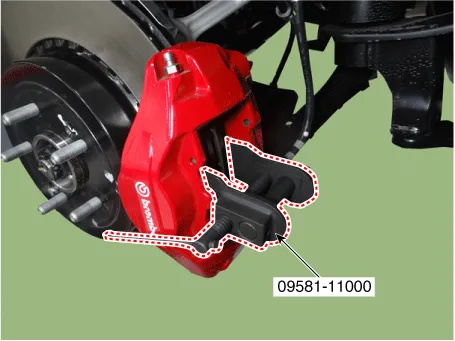
| 5. |
Use the SST (09581-11000) when installing the brake caliper assembly.
|

| 6. |
After installation, bleed the brake system. (Refer to Brake system - "Brake Bleeding Procedures") |
| [Brembo] |
Brake pad
| 1. |
Remove wheel nuts, wheel and tire (A) from hub.
|
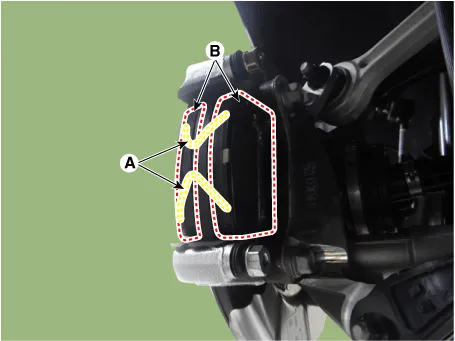
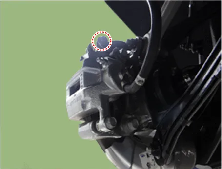
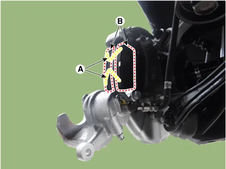
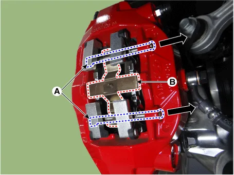
| 2. |
Push the guide pin (A) and then remove the retraction spring (B).
|
| 3. |
Install in the reverse order of removal. |
| 4. |
Use the SST (09581-11000) when installing the brake caliper assembly.
|
| 5. |
After installation, bleed the brake system. (Refer to Brake system - "Brake Bleeding Procedures") |
| Inspection |
Rear brake disc thickness check
| 1. |
Check the brake pads for wear and fade. |
| 2. |
Check the brake disc for damage and cracks. |
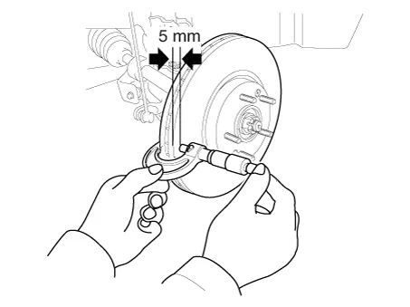
| 3. |
Remove all rust and contamination from the surface, and measure the disc thickness at 8 points, at least, at the same distance (5mm) apart from the brake disc outer circle.
|
| 4. |
If wear exceeds the limit, replace the discs and pad assembly left and right of the vehicle. |
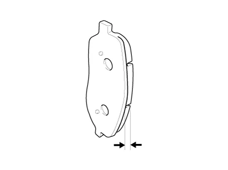
Rear Brake Pad Check
| 1. |
Check the pad wear. Measure the pad thickness and replace it, if it is less than the specified value.
|
| 2. |
Check that grease is applied to sliding contact points and check the pad and backing metal for damage. |
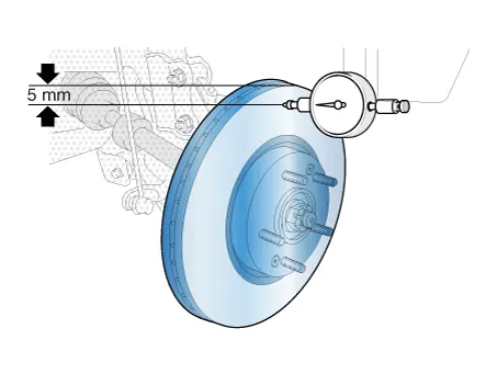
Rear brake disc runout check
| 1. |
Place a dial gauge about 5mm (0.2 in.) from the outer circumference of the brake disc, and measure the runout of the disc.
|
| 2. |
If the runout of the brake disc exceeds the limit specification, replace the disc, and then measure the runout again. |
| 3. |
If the runout does not exceed the limit specification, install the brake disc after turning it 180° and then check the brake disc again for runout. |
| 4. |
If the runout cannot be corrected by changing the position of the brake disc, replace the brake disc. |


Other information:
Kia Stinger (CK) 2018-2023 Service Manual: Front Door Belt Outside Weatherstrip
Repair procedures Replacement Put on gloves to protect your hands. • When prying with a flat-tip screwdriver or using a prying trim tool, wrap protective tap around the tool and related parts to prevent damage.Kia Stinger (CK) 2018-2023 Service Manual: Automatic transmission operation
The automatic transmission has 8 forward speeds and one reverse speed. The individual speeds are selected automatically in the D (Drive) position. WARNING To reduce the risk of serious injury or death: ALWAYS check the surrounding areas near your vehicle for people, especially children, before shifting a vehicle into D (Drive) or R (Reverse).Categories
- Manuals Home
- Kia Stinger Owners Manual
- Kia Stinger Service Manual
- New on site
- Most important about car
