Kia Stinger CK: Brake System / Stop Lamp Switch
Components and components location
| Components |
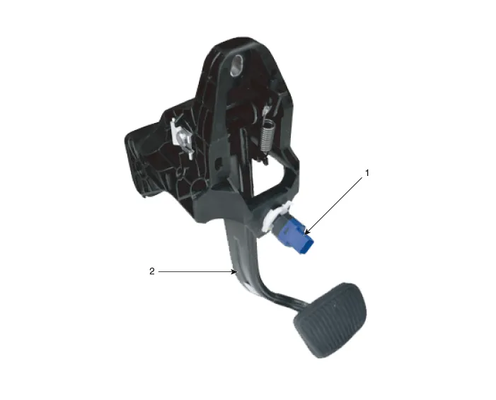
| 1. Brake lamp switch |
2. Brake pedal |
Description and operation
| Operation |
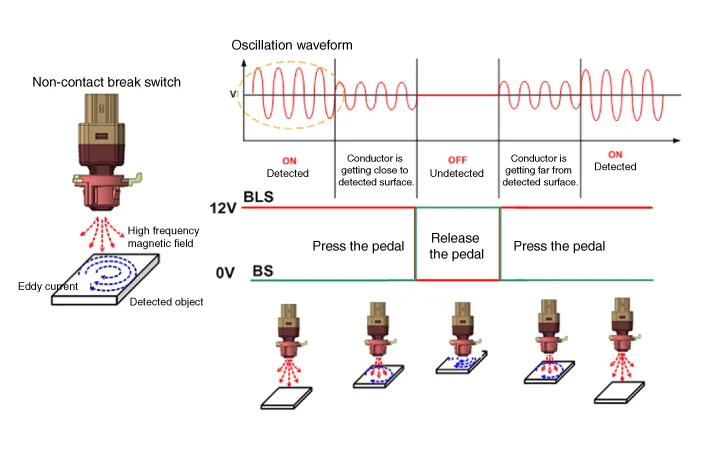
Operation principle of inductive non-contact switch
| 1. |
Use the high frequency magnetic field and the induced current that are generated by oscillation (to approved voltage) of coil in switch. |
| 2. |
The eddy current is generated on surface of metal by self inductance effect if there is metal in high frequency magnetic field. |
| 3. |
The eddy current that is generated attenuates the high frequency magnetic field as much as amount of generated by disturbing the switch's magnetic flux. |
| 4. |
ON-OFF by judging whether high voltage magnetic field is attenuates or not(caluculate the voltage difference by length between metal and coil) |
Schematic diagrams
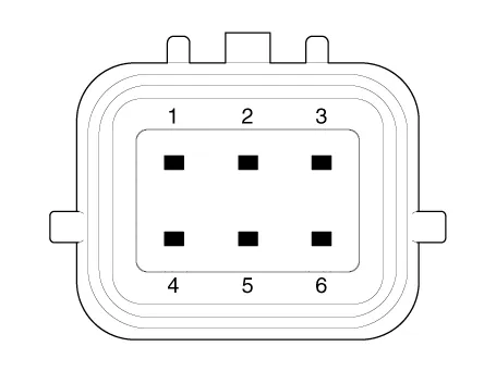
| Terminal function |

|
Pin No |
Description |
|
1 |
IGN1 |
|
2 |
IBU |
|
3 |
- |
|
4 |
B+ |
|
5 |
Stop lmap |
|
6 |
Ground |
Troubleshooting
| Troubleshooting |
| 1. |
Part diagnosis
|
| 2. |
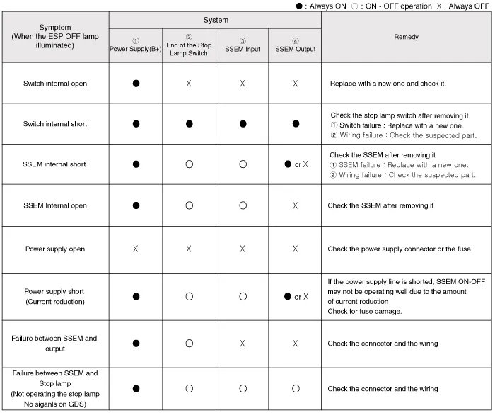
Symptom diagnosis
|
| 3. |
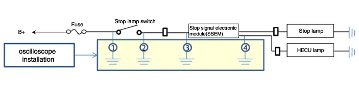
Stop lamp switch system diagnosis
SSEM : Stop Signal Electronic Module |
| 4. |
Refer to DTC guide when the related DTC codes are displayed. |
Repair procedures
| Removal |
| 1. |
Turn ignition switch OFF and disconnect the negative (-) battery cable. |
| 2. |
Remove the crash pad lower panel. (Refer to Body - "Crash Pad Lower Panel") |
| 3. |
Remove the knee airbag. (Refer to Restraint - "Knee airbag (KAB) module") |
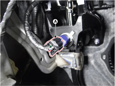
| 4. |
Disconnect the brake lamp switch connector (A).
|
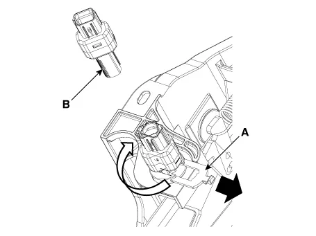
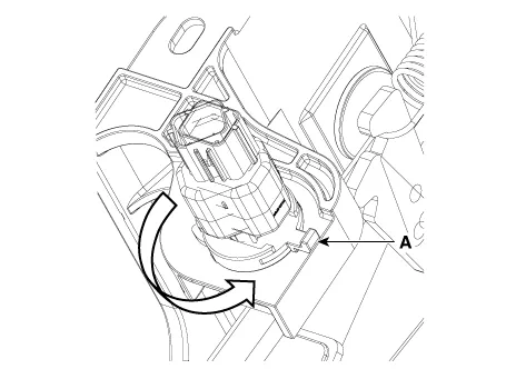
| 5. |
Pull the locking plate (A) as indicated by the arrow and then turn brake switch (B) 45° clockwise and remove it.
|
| 6. |
Inspect a removed stop lamp switch along the below procedures.
|
| Installation |
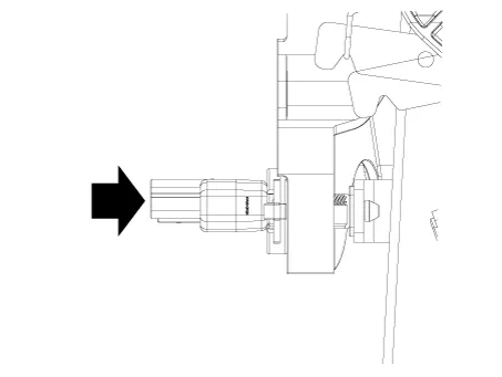
| 1. |
Fix the brake pedal arm and insert fully the brake switch so that the contact part is invisible.
|
| 2. |
After inserting, turn the brake switch 45° counterclockwise, and then assemble locking plate by pushing.
|
| 3. |
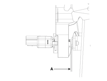
Confirm the gap between stop lamp switch and bracket.
|

| 4. |
Install the stop lamp switch connector (A).
|
| Inspection |
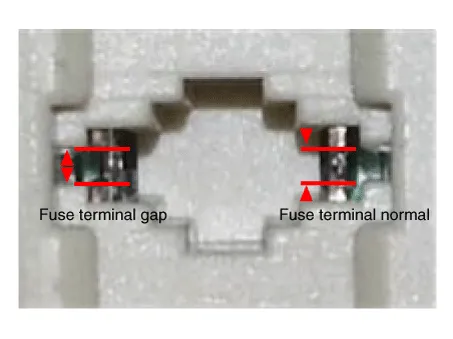
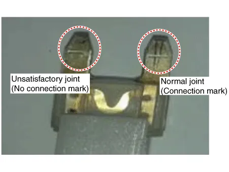
1. Fuse inspection
Mount the test fuse to the switch fuse and relay fuse part to confirm a normal joint fit.
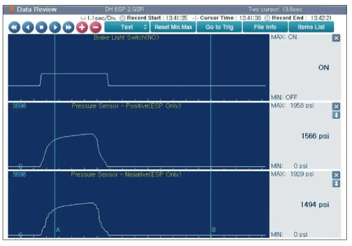
2. KDS Data Analysis
| 1. |
Analyze KDS data and check for any abnormality with the stop lamp switch.
|
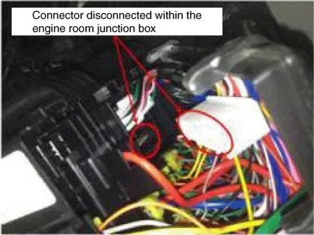
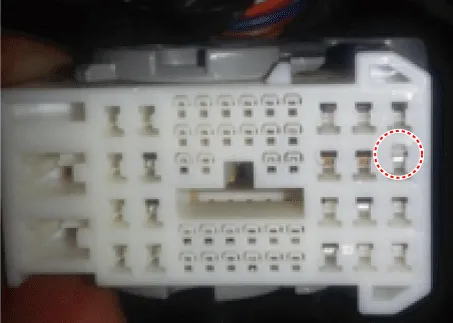
3. Inspection of connector by each part
Check for damage, terminal surge or incomplete connection in each connector.
[Engine room junction box]
[ABS/VDC control module]
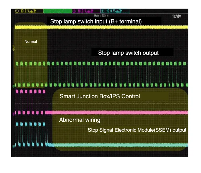
4. Inspect the stop lamp circuit
Connect probe to each terminal wire and confirm oscilloscope waveform.
[Stop lamp switch input/output]

[Oscilloscope waveform screen]


Other information:
Kia Stinger (CK) 2018-2023 Service Manual: Auto defogging system
Auto defogging reduces the probability of fogging up the inside of the windshield by automatically sensing the moisture of inside the windshield. The auto defogging system operates when the heater or air conditioning is on. The auto defogging system does not work if you push the Air intake control button, Air conditioning button, or Mode selection button with the Auto Defogging system in operation.Kia Stinger (CK) 2018-2023 Service Manual: Storage compartments
These compartments can be used to store small items required by the driver or passengers. To avoid possible theft, do not leave valuables in the storage compartment. Always keep the storage compartment covers closed while driving. Do not attempt to place so many items in the storage compartment that the storage compartment cover can not close securely.Categories
- Manuals Home
- Kia Stinger Owners Manual
- Kia Stinger Service Manual
- New on site
- Most important about car
