
Kia Stinger CK: Brake System / Brake Line
Components and components location
| Components |
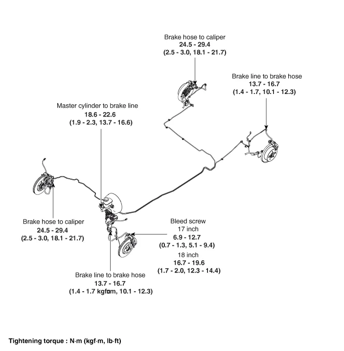
Repair procedures
| Removal |
| 1. |
Turn ignition switch OFF and disconnect the negative (-) battery cable. |
| 2. |
Remove the brake fluid from the master cylinder reservoir with a syringe.
|

| 3. |
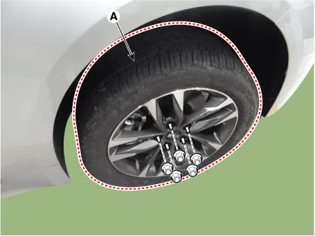
Remove wheel nuts, front/rear wheel and tire (A) from front/rear hub.
[Front] |
| 4. |
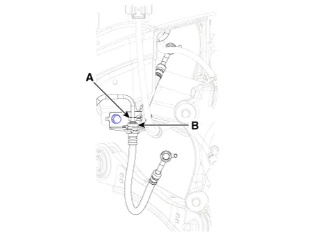
Loosen the flare nut (A) and then disconnect the tube. |
| 5. |
Disconnect the brake hose clip (B).
[Rear] |

| 6. |
Loosen the flare nut (A) and then disconnect the tube. |
| 7. |
Disconnect the brake hose clip (B).
|
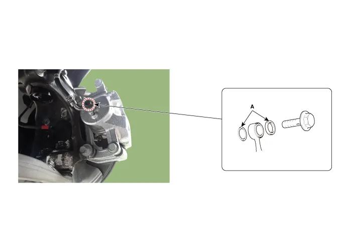
| 8. |
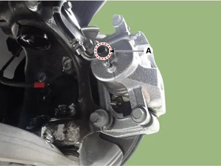
Loosen the front/rear brake cailiper hose bolt (A).
|
| Inspection |
| 1. |
Check the brake tubes for cracks, crimps and corrosion. |
| 2. |
Check the brake hoses for cracks, damage and fluid leakage. |
| 3. |
Check the brake tube flare nuts for damage and fluid leakage. |
| 4. |
Check brake hose mounting bracket for crack or deformation. |
| Installation |
| 1. |
Install in the reverse order of removal.
|
| 2. |
After installation, bleed the brake system. (Refer to Brake system - "Brake Bleeding Procedures") |
| 3. |
Check the spilled brake oil. |


Other information:
Kia Stinger (CK) 2018-2023 Service Manual: Auto Defogging Sensor (DATC only)
Description and operation Description Installed on the windshield glass, the auto defogging sensor judges and sends signal to blow out wind for defogging if moisture occurs. On receiving the signal from the sensor, the air conditioner control module restrains moisture and eliminates fog by controlling the intake actuator, A/C, auto defogging actuator, blower motor rpm, and mode actuator.Components and components location Components ① ECM ② Battery ③ Alternator ④ Starter ⑤ Instrument Cluster ⑥ Ignition switch or start/stop button ⑦ Battery sensor ⑧ Hood switch Description and operation Description The charging system included a battery, an alternator with a built-in regulator, and the charging indicator light and wire.Categories
- Manuals Home
- Kia Stinger Owners Manual
- Kia Stinger Service Manual
- New on site
- Most important about car
