Kia Stinger CK: Engine Control System / Manifold Absolute Pressure Sensor (MAPS)
Specifications
Item
|
Specification
|
Output Voltage (V)
|
5
|
Pressure (KPa)
|
32.5 - 284
|
Operating Voltage (V)
|
4.5 - 5.5
|
Pressure
[kPa (kgf/cm², psi)]
|
Output Voltage (Vref = 5V)
|
32.5 (0.33, 4.71)
|
0.5
|
70 (0.71, 10.1)
|
1.1
|
270 (2.75, 39.1)
|
4.3
|
284 (2.89, 41.1)
|
4.5
|
Description and operation
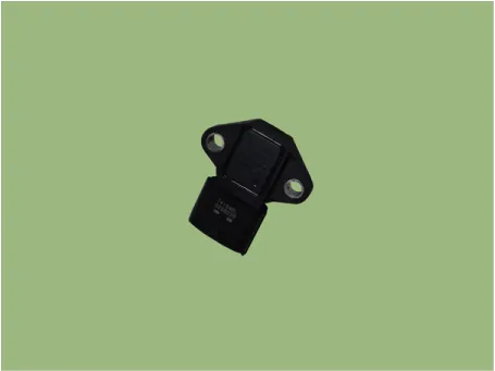
Manifold Absolute Pressure Sensor (MAPS) is a speed-density type sensor installed
on the surge tank. It senses absolute pressure of the surge tank and transfers the
analog signal proportional to the pressure to the ECM. By using this signal, the
ECM calculates the intake air quantity and engine speed.
The MAPS consists of a piezo-electric element and a hybrid IC amplifying the
element output signal. This silicon diaphragm type element has pressure sensitive
variable resistor effect of semi-conductor. One side of silicon diaphragm is 100%
vacuum and manifold pressure is applied on the other side. Hence, output is gained
from the silicon variation in proportion to the pressure change.
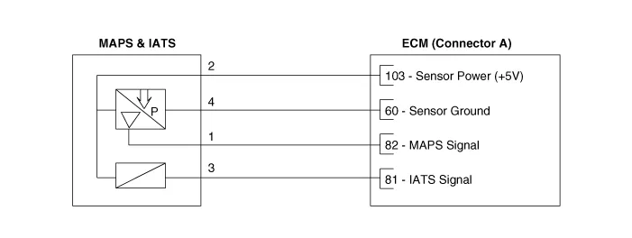
Schematic diagrams
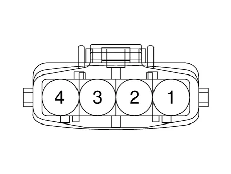
Harness Connector
Repair procedures
| 1. |
Connect the KDS on the Data Link Connector (DLC).
|
| 2. |
Measure the output voltage of the MAPS during idle with IG ON.
Pressure
[kPa (kgf/cm², psi)]
|
Output Voltage (V) [Vref=5V]
|
20.0 (0.20, 2.9)
|
0.79
|
46.7 (0.47, 6.77)
|
1.84
|
101.3 (1.03, 14.7)
|
4.0
|
|
| 1. |
Switch "OFF" the ignition and disconnect the negative (-) battery terminal.
|
| 2. |
Remove the engine cover.
(Refer to Engine Mechanical System - "Engine Cover")
|
| 3. |
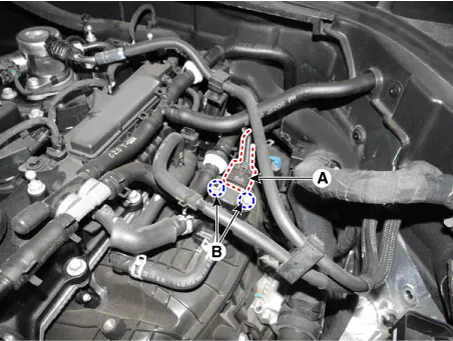
Disconnect the manifold absolute pressure sensor connector (A).
|
| 4. |
Remove the installation bolts (B), and then remove the sensor from the
intake manifold.
|
Manifold absolute pressure sensor installation bolt :
9.8 - 11.8 N·m (1.0 - 1.2 kgf·m, 7.2 - 8.7 lb·ft)
|
|
| • |
Install the component to the specified torques.
|
| • |
Note that internal damage may occur when the component is dropped.
If the component has been dropped, inspect before installing.
|
| • |
Insert the sensor in the installation hole and be careful not
to damage it.
|
|
| 1. |
Install in the reverse order of removal.
|
Other information:
Kia Stinger (CK) 2018-2023 Service Manual: Air bag inflation conditions
Front air bags
Front air bags are designed to inflate in a frontal collision depending on the
intensity, speed or angles of impact of the front collision.
Side and/or curtain air bags
Side and/or curtain air bags are designed to inflate when an impact is detected
by side collision sensors depending on the strength, speed or angles of impact resulting
from a side impact collision.
Kia Stinger (CK) 2018-2023 Service Manual: Blind-Spot Collision Warning (BCW) Warning Lamp
Components and components location
Components
1. Side repeater lamp
2. BCW Indicator
3. AVM Camera
4. Puddle lamp
Repair procedures
Removal
1.
Disconnect the negative (-) battery terminal.
2.
Remove mirror (A) to the direction as shown in the picture using (-)
screw driver.


