Kia Stinger CK: Smart Key System / Smart Key Diagnostic
Repair procedures
| Inspection |
| 1. |
In the body electrical system, failure can be quickly diagnosed by using the vehicle diagnostic system (KDS). The diagnostic system (KDS) provides the following information.
|
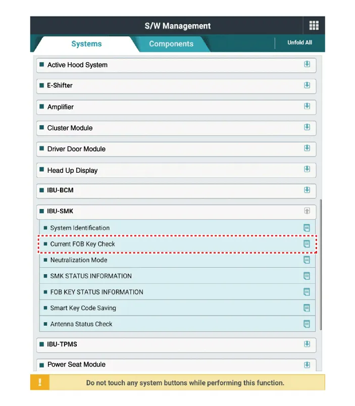
| 2. |
Select the "Car model" and the 'IBU-SMK' to be checked in order to check the vehicle with the tester. |
| 3. |
Select the 'Current Data' menu to search the current state of the input/output data. |
| 4. |
If you want to check each module operation forcefully, select "Actuation test". |
Antenna Actuation Diagnosis
| 1. |
Connect the cable of KDS to the data link connector in driver side crash pad lower panel. |
| 2. |
After IG ON, select the "Actation Test". |
| 3. |
Set the smart key near the related antenna and operate it with a KDS. |
| 4. |
If the LED of smart key is blinking, the smart key is normal. |
| 5. |
If the LED of smart key is not blinking, check the voltage of smart key battery. |
| 6. |
Antenna actuation
|
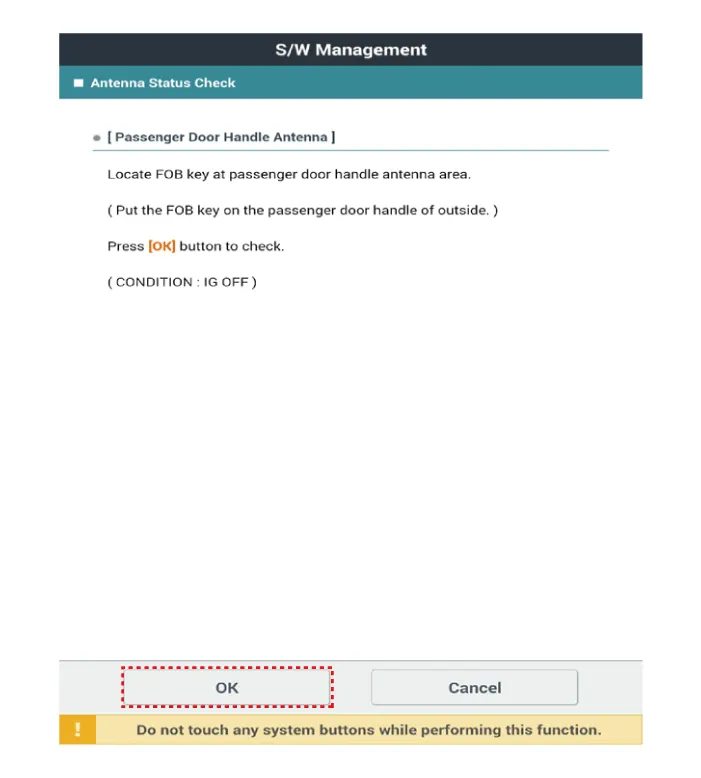
Antenna Status Check
| 1. |
Connect the cable of KDS to the data link connector in driver side crash pad lower panel. |
| 2. |
Select the "Antenna Status Check".
|
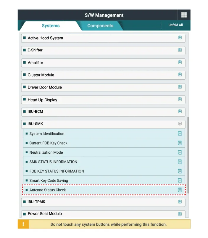
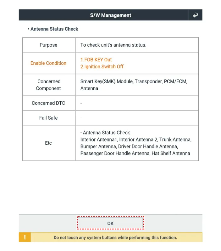
| 3. |
After IG ON, select the "Antenna Status Check".
|
| 4. |
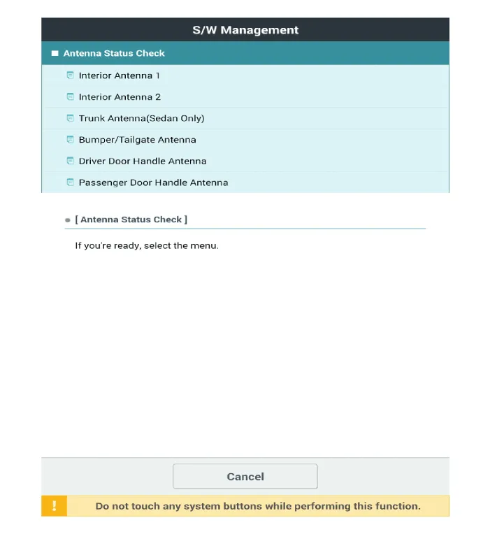
Set the smart key near the related antenna and operate it with a KDS.
|
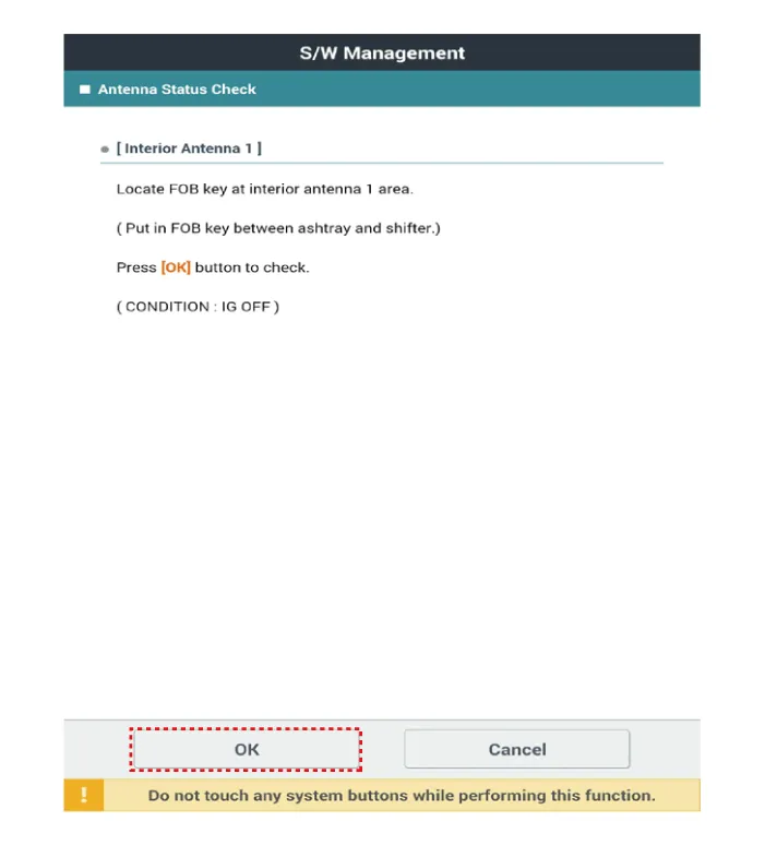
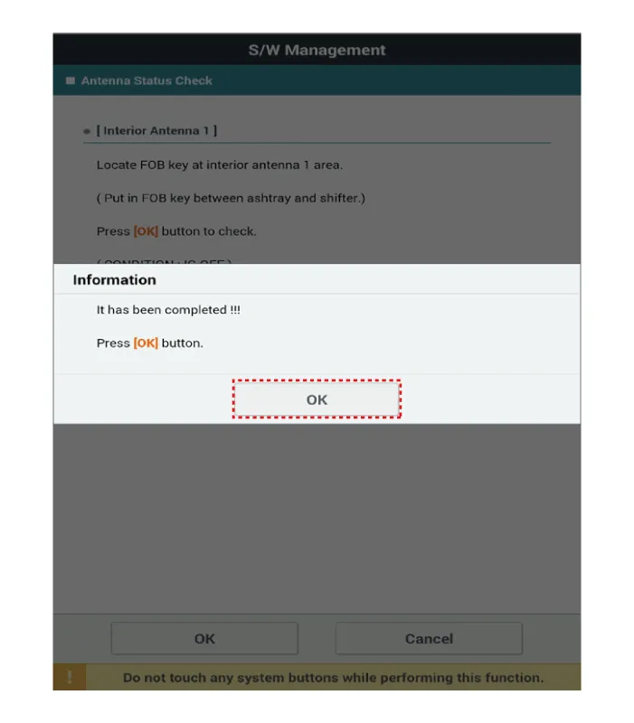
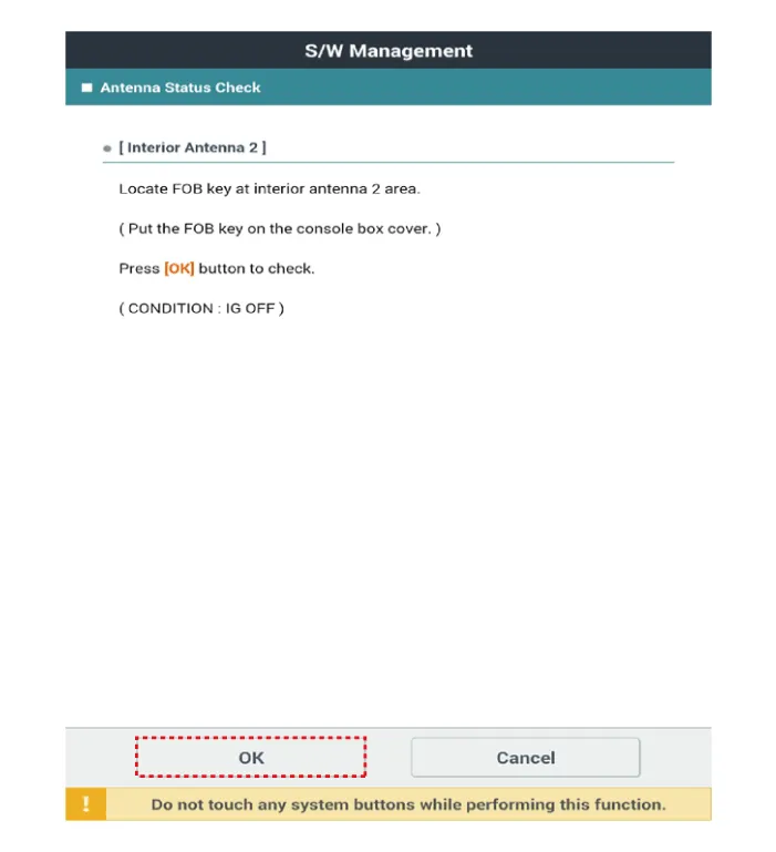
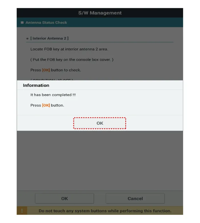
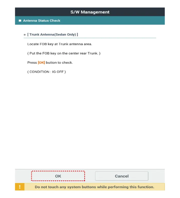
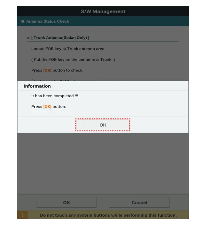
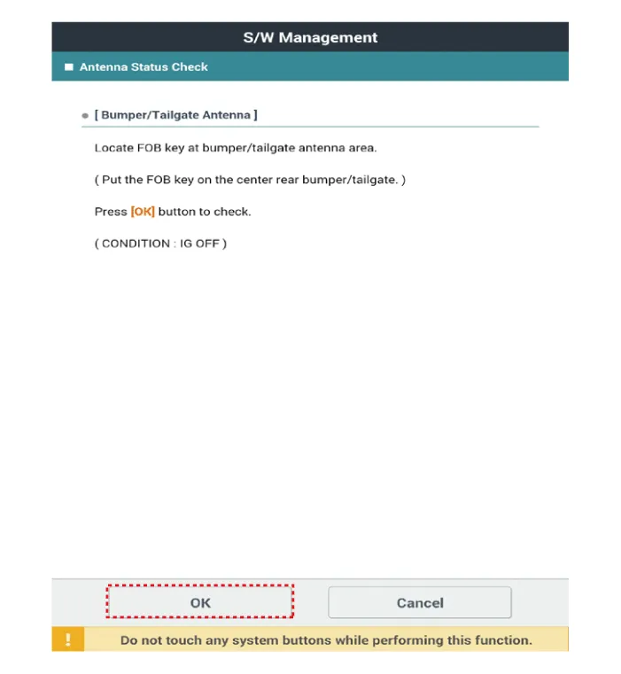
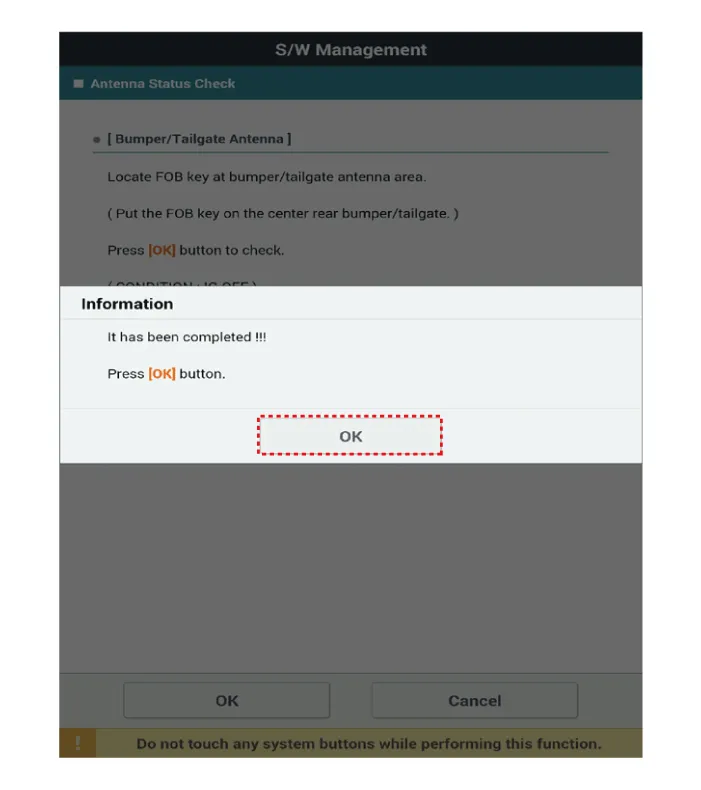
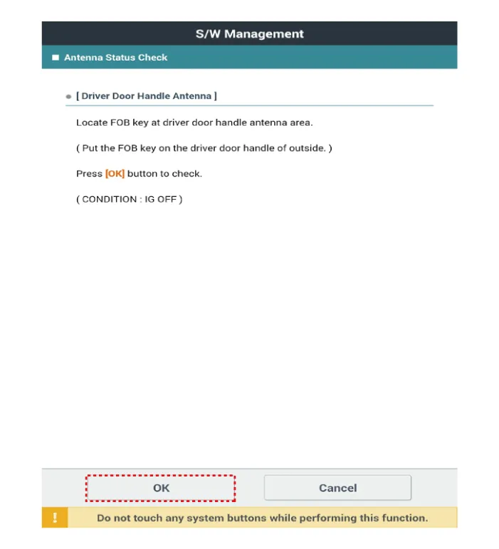

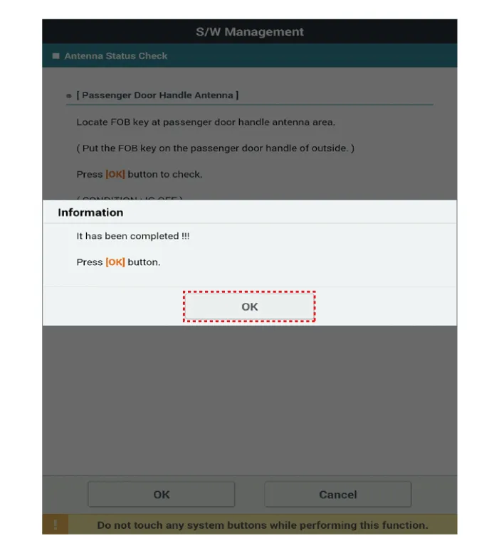
| 5. |
If the smart key runs normal , the related antenna, smart key(transmission, reception) and exterior receiver are normal. |
| 6. |
Antenna status
|
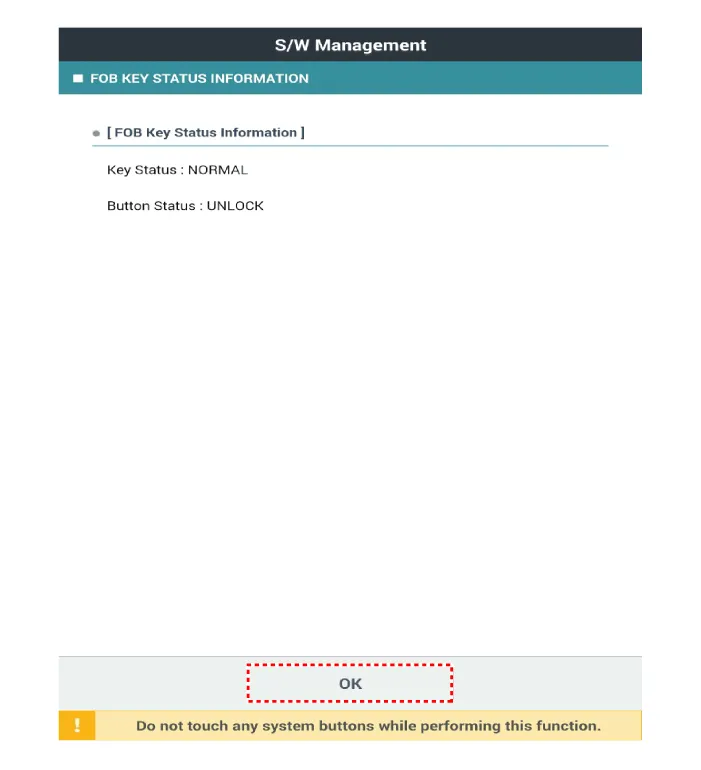
FOB Status Check
| 1. |
Connect the cable of KDS to the data link connector in driver side crash pad lower panel. |
| 2. |
After IG ON, select the "FOB KEY STATUS INFO".
|

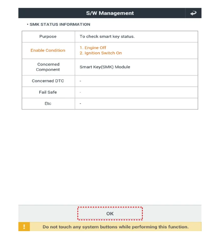
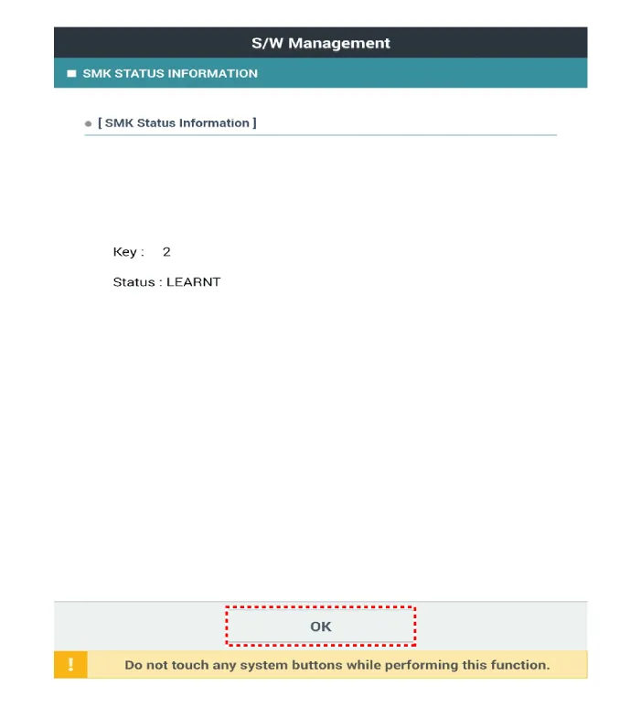
Smart Key Status Check
| 1. |
Connect the cable of KDS to the data link connector in driver side crash pad lower panel. |
| 2. |
After IG ON, select the "SMK STATUS INFO".
|

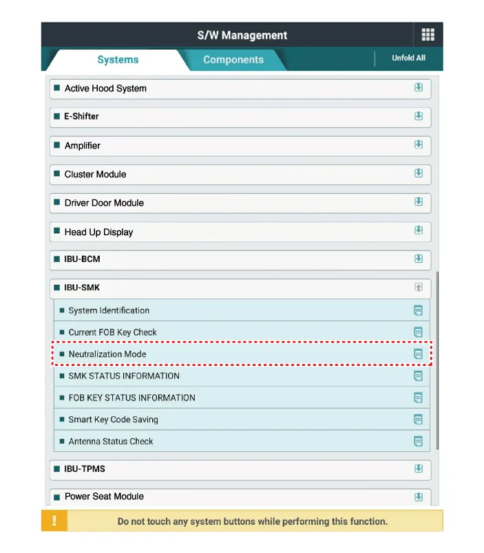
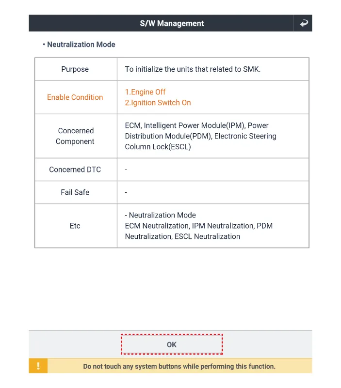
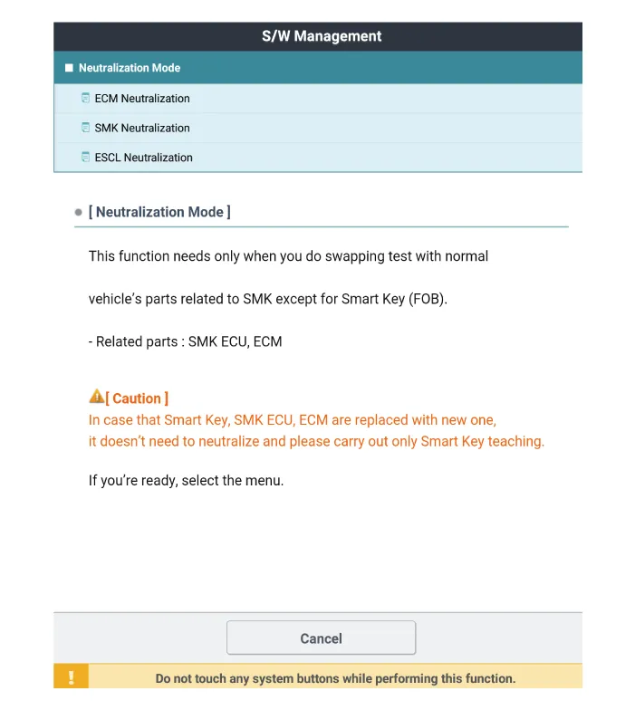
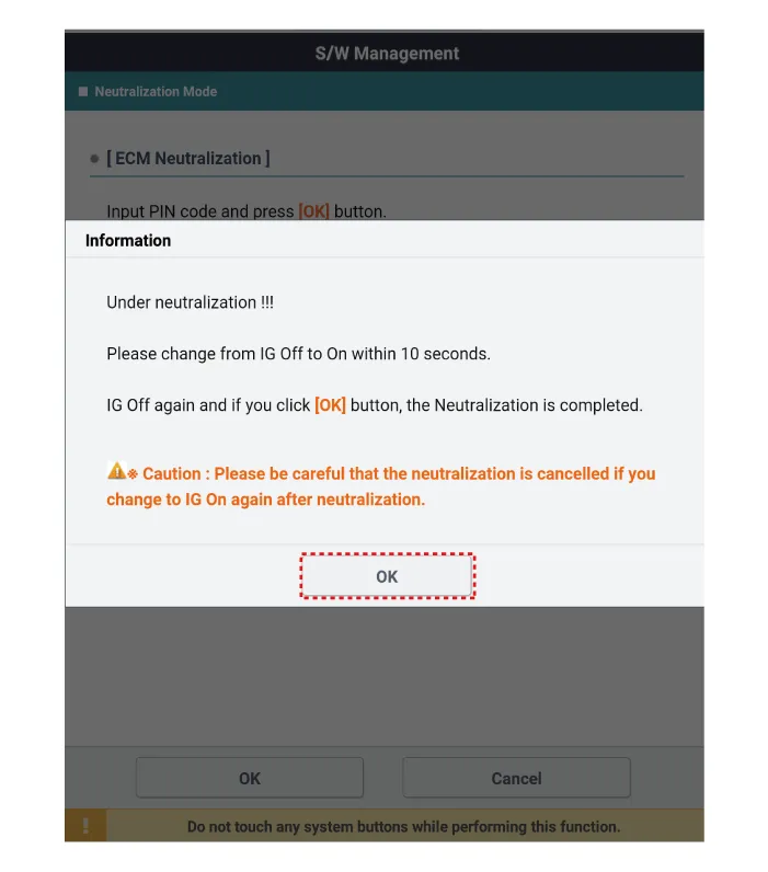
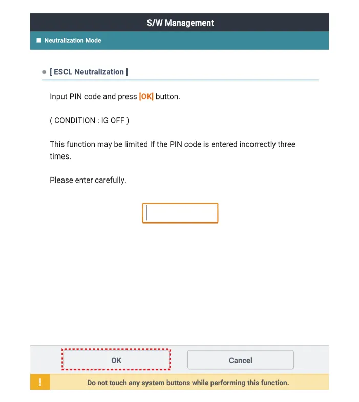
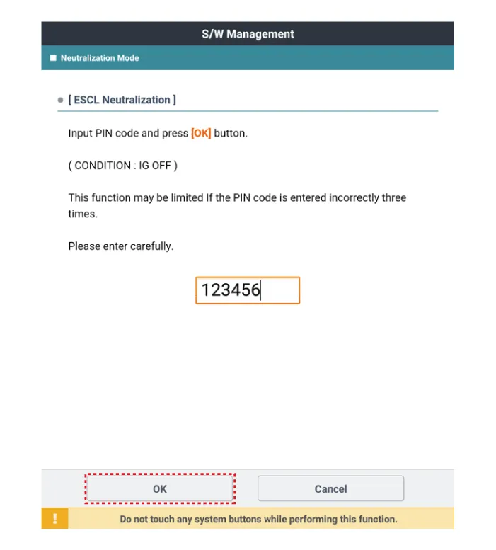
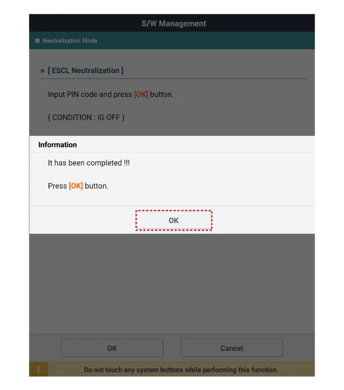
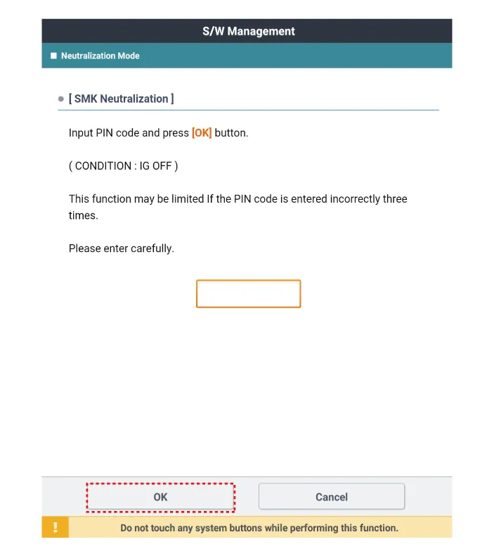
Neutralization Status Check
| 1. |
Connect the cable of KDS to the data link connector in driver side crash pad lower panel. |
| 2. |
After IG ON, select the "Neutralization mode".
|


Other information:
Components and components location Component Location 1. Cowl top cover Repair procedures Replacement Put on gloves to protect your hands. • Use a plastic panel removal tool to remove interior trim pieces without marring the surface.■ Head lamp - Type A 1. Remove the service cover clip on the wheel housing. 2. Remove the headlamp bulb cover by turning it counterclockwise. 3. Disconnect the headlamp bulb socket-connector. 4. Remove the bulb-socket from the headlamp assembly by turning the bulb-socket counterclockwise until the tabs on the bulb-socket align with the slots on the headlamp assembly.Categories
- Manuals Home
- Kia Stinger Owners Manual
- Kia Stinger Service Manual
- New on site
- Most important about car
