Kia Stinger CK: Smart Key System / Smart Key Unit
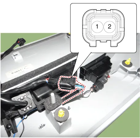
Components and components location
| Components |
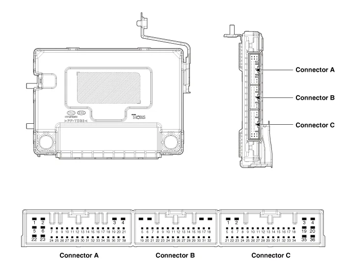
Connector Pin Information
|
No. |
Connector A |
Connector B |
Connector C |
|
1 |
- |
B-CAN (Low) |
Front wiper low bus switch_Input |
|
2 |
Mirror power_Input |
B-CAN (High) |
Ground (Power) |
|
3 |
P-CAN (Low) |
PDW-F_Power_Output |
Battery (Power) |
|
4 |
P-CAN (High) |
PDW-R_Power_Output |
Battery (ECU) |
|
5 |
- |
Ground (ECU) |
Driver outside handle switch_Input |
|
6 |
Right mirror unfold_Output |
PDW Switch_Input |
Position_Input(A/T Option) IGN Lock switch_Input (M/T Option) |
|
7 |
Right mirror horizontal_Output |
PDW (Option)_Input |
Interior antenna1 (-)_Output |
|
8 |
Immobilizer power_Output |
- |
Bumper antenna (-)_Output |
|
9 |
Immobilizer ground_Output |
- |
Interior antenna2 (-)_Output |
|
10 |
Brake switch_Input |
- |
Assist outside handle antenna (-)_Output |
|
11 |
ESCL Enable_Output |
Front wiper high relay_Output |
Trunk interior antenna3 (-)_Output |
|
12 |
Brake switch fuse_Input |
Rear left seat belt indicator_Output |
Driver outside handle anntenna (-)_Output |
|
13 |
Fog switch_Input |
Assist seat belt indicator_Output |
- |
|
14 |
Light switch_Input |
- |
COM (ESCL) |
|
15 |
Front wiper volume switch_Input |
LF Searching_Output |
Auto light sensor power_Output |
|
16 |
PDW Switch indicator_Output |
- |
ACC_Input |
|
17 |
SSB Ring illumination_Output |
SSB Switch1_Input |
IGN1 Relay_Output |
|
18 |
LIN CAN (PDW) |
PDW_Power_Input |
ACC Relay_Output |
|
19 |
- |
Security indicator_Output |
ESCL (-)_Output |
|
20 |
Engine RPM_Input |
Sunroof status_Input |
ESCL (+)_Output |
|
21 |
Wheel speed sensor_Input |
Rain sensor (Option)_Input |
Assist outside handle switch_Input |
|
22 |
- |
Wiper parking switch_Input |
- |
|
23 |
Right mirror fold_Output |
Wiper power relay_Output |
Interior antenna1 (+)_Output |
|
24 |
Right mirror vertical_Output |
Front wiper low relay_Output |
Bumper antenna (+)_Output |
|
25 |
- |
- |
Interior antenna2 (+)_Output |
|
26 |
Puddle pocket lamp_Output |
- |
Assist outside handle antenna (+)_Output |
|
27 |
Start feedback_Input |
Rear center seat belt indicator_Output |
Trunk interior antenna3 (+)_Output |
|
28 |
- |
- |
Driver outside handle anntenna (+)_Output |
|
29 |
Starter relay_Output |
SSB Symbo illumination (-)_Output |
COM (EMS) |
|
30 |
Headlamp high switch |
Rear right seat belt indicator_Output |
Auto light sensor ground_Output |
|
31 |
Front wiper switch |
SSB Switch2_Input |
Auto light sensor signal_Input |
|
32 |
- |
ESCL Unlock switch_Input |
IGN1_Input |
|
33 |
Multifunction switch ground_Input |
|
IGN2_Input |
|
34 |
External buzzer_Output |
IGN2 Relay_Output |
|
|
35 |
SSB Symbo illumination (+)_Output |
Front washer switch_Input |
|
|
36 |
LIN CAN (Rain sensor) |
Battery (+)_ESCL |
|
|
37 |
- |
|
|
|
38 |
ATM Solenoin_Output |
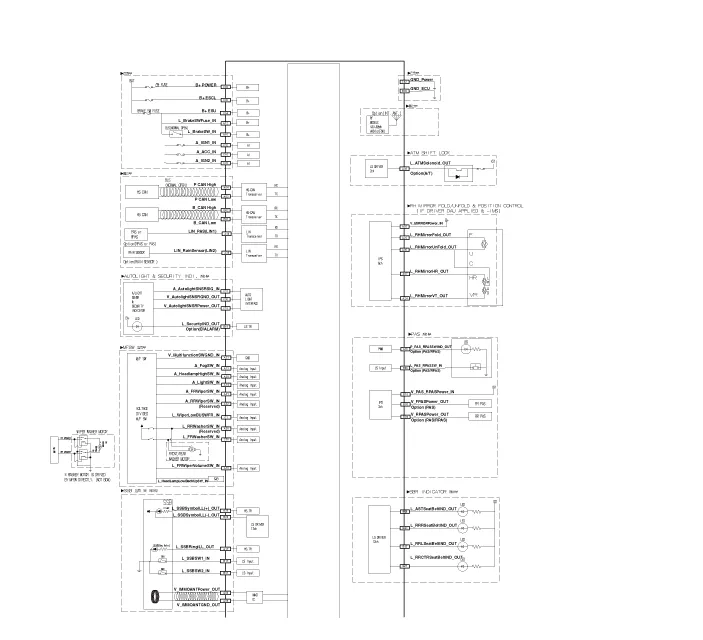
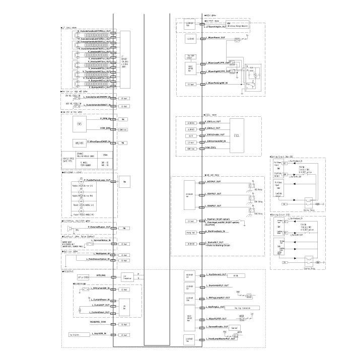
Schematic diagrams
| Circuit Diagram |
Repair procedures
| Removal |
Put on gloves to prevent hand injuries. |
|
Integrated Body control Unit (IBU)
| 1. |
Disconnect the negative (-) battery terminal. |
| 2. |
Remove the glove box housing. (Refer to Body - "Glove Box Housing") |
| 3. |
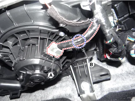
Disconnect the blower motor connector (A) after removing the mounting clip (B).
|
| 4. |
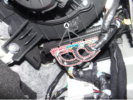
Disconnect the integrated body control unit connectors (A).
|
| 5. |
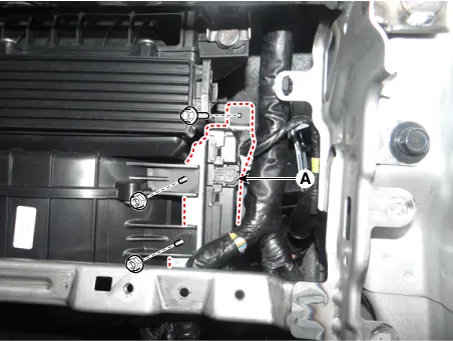
Remove the integrated body control unit (A) after loosening the mounting nuts and bolt.
|
| 6. |
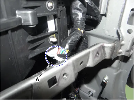
Remove the wiring harness mounting clip (A) from the integrated body control unit.
|
Interior 1 Antenna
| 1. |
Disconnect the negative (-) battery terminal. |
| 2. |
Remove the floor console assembly. (Refer to Body - "Floor Console Assembly") |
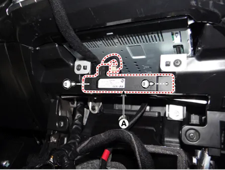
| 3. |
Remove the interior 1 antenna (A) after disconnecting the connector and loosening the mounting screws.
|
Interior 2 Antenna
| 1. |
Disconnect the negative (-) battery terminal. |
| 2. |
Remove the floor console assembly. (Refer to Body - "Floor Console Assembly") |
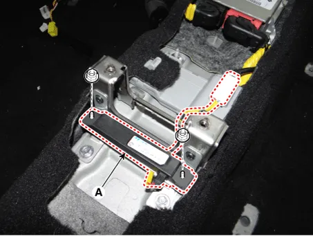
| 3. |
Remove the interior 2 antenna (A) after disconnecting the connector and loosening the mounting nuts.
|
Tailgate Antenna
| 1. |
Disconnect the negative (-) battery terminal. |
| 2. |
Remove the rear transverse trim. (Reger to Body - " Rear Transverse Trim") |
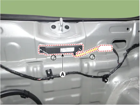
| 3. |
Remove the tailgate antenna (A) after disconnecting the connector and loosening the mounting nuts.
|
Rear Bumper Antenna
| 1. |
Disconnect the negative (-) battery terminal. |
| 2. |
Remove the rear bumper beam assembly. (Refer to Body - "Rear Bumper Beam Assembly") |
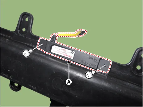
| 3. |
Remove the rear bumper antenna (A) after loosening the mounting screws.
|
Buzzer
| 1. |
Disconnect the negative (-) battery terminal. |
| 2. |
Remove the front wheel guard [LH]. (Refer to Body - "Front Wheel Guard") |
| 3. |
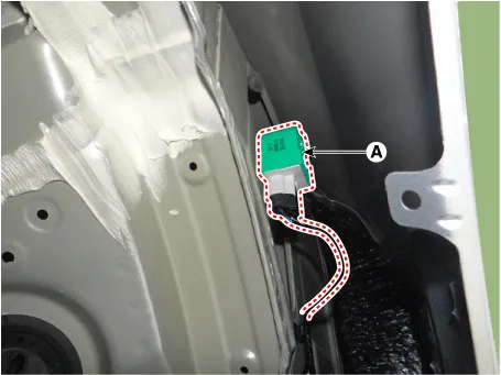
Remove the buzzer (A) after disconnecting the connector.
|
Door Outside Handle
| 1. |
Disconnect the negative (-) battery terminal. |
| 2. |
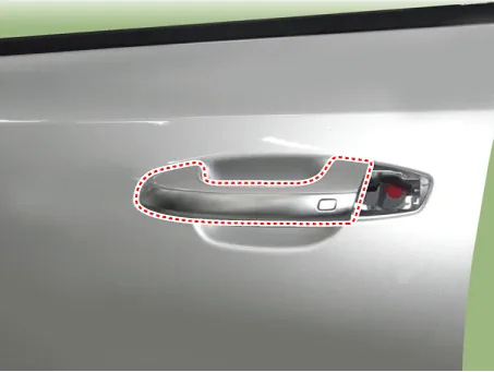
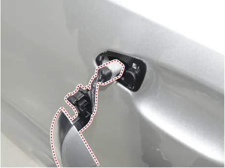
Remove the front door outside handle. (Refer to Body - "Front Door Outside Handle")
|
Tailgate Open Switch
| 1. |
Disconnect the negative (-) battery terminal. |
| 2. |
Remove the tailgate back panel. (Refer to Body - "Tailgate Back Panel") |
| 3. |
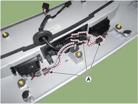
Disconnect the license lamp connectors (A).
|
| 4. |
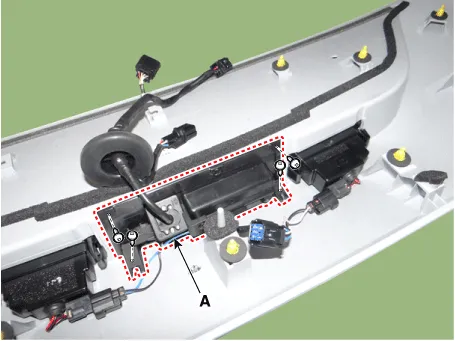
Remove the tailgate outside handle assembly (A) after loosening the mounting screws.
|
| 5. |
Remove the tailgate open switch (A) after loosening the mounting screws.
|
| Inspection |
Smart Key Unit
(Refer to Smart Key System - "Smart Key Diagnostic")
Smart Key Switch
(Refer to Smart Key System - "Smart Key Diagnostic")
Antenna
(Refer to Smart Key System - "Smart Key Diagnostic")
Door Outside Handle
| 1. |
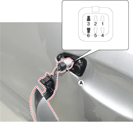
Disconnect the front door outside handle connector (A).
|
| 2. |
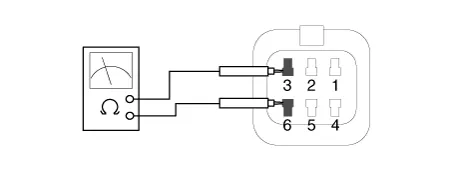
Check for continuity between terminals No 3 and No 6.
|
Tailgate Open Switch
| 1. |
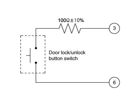
Check for continuity between the tailgate open switch terminals.
|
| 2. |
If continuity is not specified, inspect the switch.
|
| Installation |
Integrated Body control Unit (IBU)
| 1. |
Install the wiring harness mounting clip from the integrated body control unit. |
| 2. |
Install the integrated body control unit. |
| 3. |
Connect the integrated body control unit connectors. |
| 4. |
Connect the blower motor connector and clip. |
| 5. |
Install the glove box housing. |
| 6. |
Connect the negative (-) battery terminal and check the smart key system. |
Interior 1 Antenna
| 1. |
Install the interior 1 antenna after connecting the connector. |
| 2. |
Install the floor console assembly. |
| 3. |
Connect the negative (-) battery terminal and check the smart key system. |
Interior 2 Antenna
| 1. |
Install the interior 2 antenna after connecting the connector. |
| 2. |
Install the floor console assembly. |
| 3. |
Connect the negative (-) battery terminal and check the smart key system. |
Tailgate Antenna
| 1. |
Install the tailgate antenna after connecting the connector. |
| 2. |
Install the rear transverse trim. |
| 3. |
Connect the negative (-) battery terminal and check the smart key system. |
Rear Bumper Antenna
| 1. |
Install the rear bumper antenna after connecting the connector. |
| 2. |
Install the rear bumper beam assembly. |
| 3. |
Connect the negative (-) battery terminal and check the smart key system. |
Buzzer
| 1. |
Install the buzzer after connecting the connector. |
| 2. |
Install the front wheel guard [LH]. |
| 3. |
Connect the negative (-) battery terminal and check the smart key system. |
Door Outside Handle
| 1. |
Install the front door outside handle. |
| 2. |
Connect the negative (-) battery terminal and check the smart key system. |
Tailgate Open Switch
| 1. |
Install the tailgate open switch. |
| 2. |
Install the tailgate outside handle assembly. |
| 3. |
Connect the license lamp connectors. |
| 4. |
Install the tailgate back panel. |
| 5. |
Connect the negative (-) battery terminal and check the smart key system. |
Other information:
Kia Stinger (CK) 2018-2023 Service Manual: Exhaust Emission Control System
Description and operation Description Exhaust emissions (CO, HC, NOx) are controlled by a combination of engine modifications and the addition of special control components. Modifications to the combustion chamber, intake manifold, camshaft and ignition system form the basic control system. These items have been integrated into a highly effective system which controls exhaust emissions while maintaining good drivability and fuel economy.Kia Stinger (CK) 2018-2023 Service Manual: Power Door Mirror Switch
Components and components location Components Schematic diagrams Circuit Diagram Front Safety + IMS Type Front Safety + Non-IMS Type Repair procedures Inspection Diagnosis With KDS 1. The body electrical system can be quickly diagnosed for failed parts by using vehicle diagnostic system (KDS).Categories
- Manuals Home
- Kia Stinger Owners Manual
- Kia Stinger Service Manual
- New on site
- Most important about car


