Kia Stinger CK: Body (Interior and Exterior) / Floor Carpet
Components and components location
| Component Location |
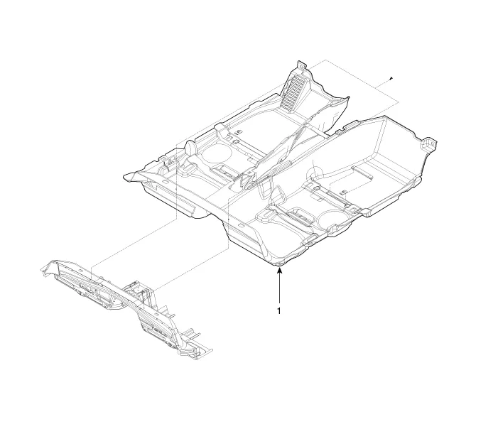
| 1. Floor carpet assembly |
Repair procedures
| Replacement |
Put on gloves to protect your hands. |

|

| 1. |
Remove the front seat assembly. (Refer to Front Seat - "Front Seat Assembly") |
| 2. |
Remove the rear seat assembly. (Refer to Rear Seat - "Rear Seat Assembly") |
| 3. |
Remove the floor console assembly. (Refer to Floor Console - "Floor Console Assembly") |
| 4. |
Carefully remove the front door body side weather strip. |
| 5. |
Carefully remove the rear door body side weatherstrip. |
| 6. |
Remove the front door scuff trim (A) by using a remover.
|
| 7. |
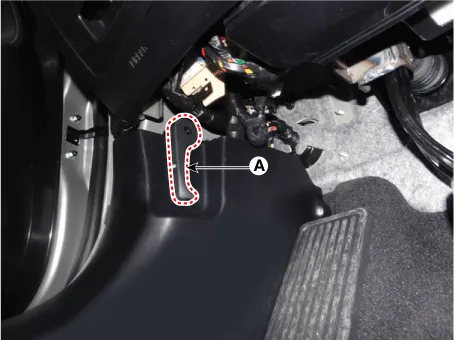
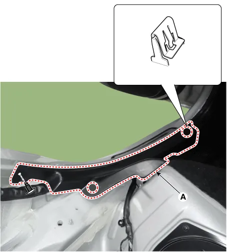
Remove the hood release handle (A).
|
| 8. |
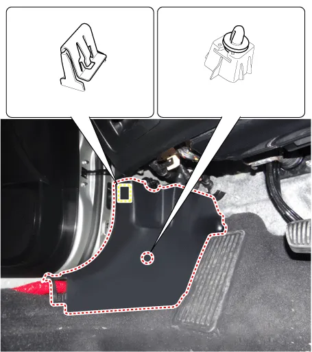
Remove the cowl side trim (A) by using a remover.
|
| 9. |
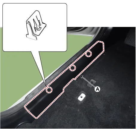
Remove the rear door scuff trim (A) after loosening the mounting clip.
|
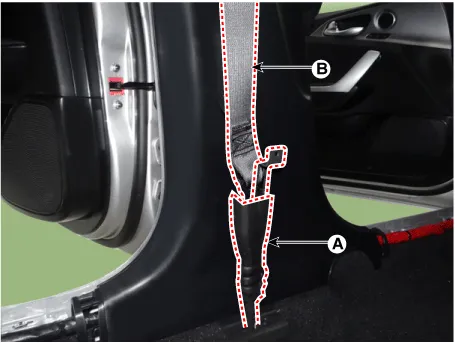
| 10. |
Remove the seat belt (B) from the EFD system by using the SST (0K888-D4200).
|
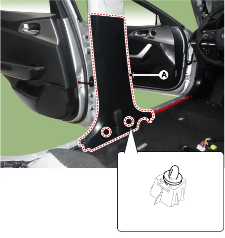
| 11. |
Remove the center pillar lower trim (A) by using a remover.
|
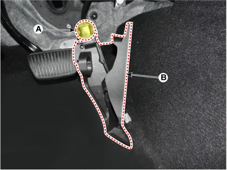
| 12. |
Remove the accelerator pedal mounting cap (A).
|
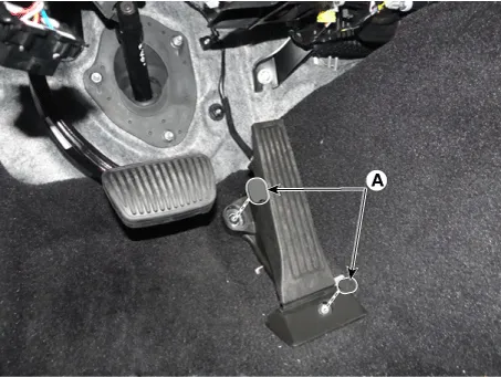
| 13. |
Separate the accelerator pedal (A) after loosening the mounting bolts.
|

| 14. |
Remove the accelerator pedal (B) after disconnecting the connector (A).
|
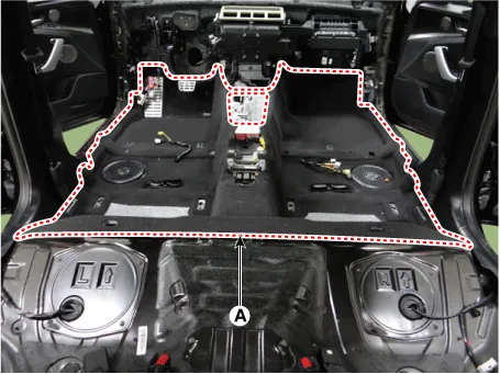
| 15. |
Remove the floor carpet assembly (A).
|
| 16. |
Install in the reverse order of removal.
|


Other information:
Repair procedures Removal [Rear upper arm rear] 1. Remove wheel nuts, wheel and tire (A) from hub. Tightening torque: 107.9 - 127.5 N·m (11.0 - 13.0 kgf·m, 79.6 - 94.0 lb·ft) Be careful not to damage the wheel bolts when removing the wheel and tire (A).Components and components location Components 1. Front pillar trim 2. Center pillar upper trim 3. Rear pillar trim 4. Cowl side trim 5. Front door scuff trim 6. Rear door scuff trim 7. Center pillar lower trim 8. Front door step trim 9. Rear door step trimCategories
- Manuals Home
- Kia Stinger Owners Manual
- Kia Stinger Service Manual
- New on site
- Most important about car
