Kia Stinger CK: Timing System / Timing Chain Cover
Repair procedures
| Removal |
In case of removing the high pressure fuel pump, high pressure fuel pipe, delivery pipe, and injector, there may be injury caused by leakage of the high pressure fuel. So don’t do any repair work right after engine stops. |

|

Mark all wiring and hoses to avoid misconnection. |

| 1. |
Disconnect the battery negative terminal. |
| 2. |
Remove the engine cover. (Refer to Engine and Transmission Assembly - "Engine Cover") |
| 3. |
Remove the engine room front under cover. (Refer to Engine and Transmission Assembly - "Engine Room Under Cover") |
| 4. |
Remove the drive belt. (Refer to Drive Belt System - "Drive Belt") |
| 5. |
Remove the water pump pulley. (Refer to Cooling System - "Water Pump") |
| 6. |
Remove the drive belt tensioner. (Refer to Drive Belt System - "Drive belt Tensioner") |
| 7. |
Remove the crankshaft damper pulley. (Refer to Drive Belt System - "Crankshaft Damper Pulley") |
| 8. |
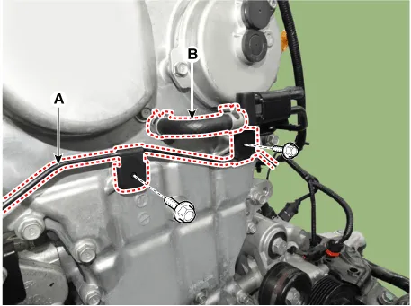
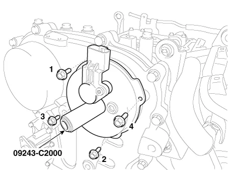
Remove the vacuum pipe (A) and then disconnect the air vent lower hose (B).
|
| 9. |
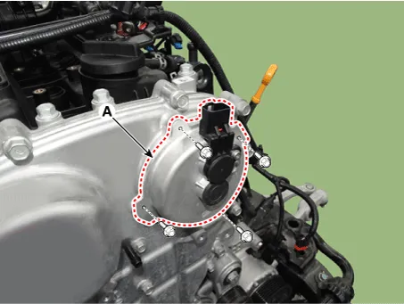
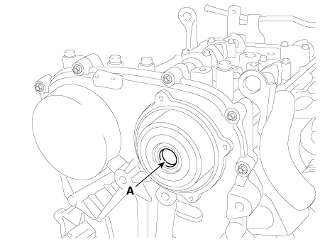
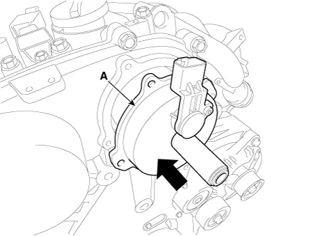
Remove the E-CVVT cover (A).
|
| 10. |
Remove the oil pan. (Refer to Lubrication System - "Oil Pan") |
| 11. |
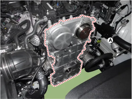
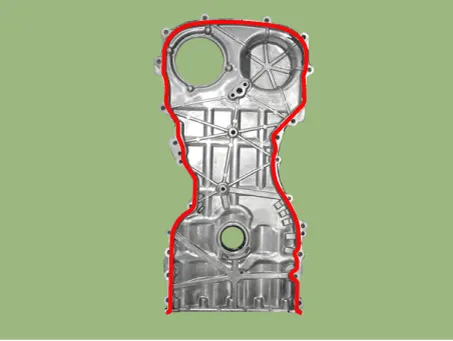
Remove the timing chain cover (A) by gently prying the portions between the cylinder head and cylinder block.
|
| Inspection |
| 1. |
Check if the oil flows inside the E-CVVT cover. If the oil flows inside the E-CVVT cover, replace the E-CVVT cover. |
| 2. |
Check the connector brush wear condition. If the brush is worn down, replace the E-CVVT cover assembly. |
| Installation |
| 1. |
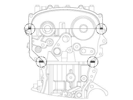
Install the timing chain cover.
|
| 2. |
Install the front oil seal. (Refer to Timing System - "Front Oil Seal") |
| 3. |
Install the drive belt tensioner. (Refer to Drive Belt System - "Drive Belt Tensioner") |
| 4. |
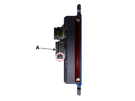
Remove it by breaking the center of E-CVVT motor plug (A).
|
| 5. |
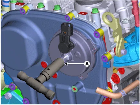
Clean the E-CVVT motor plug mounting surface (A) with oil cleaner.
|
| 6. |
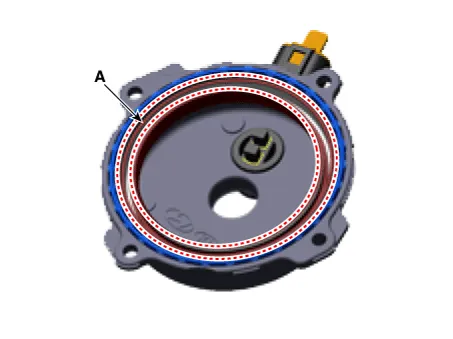
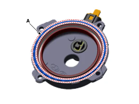
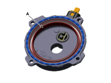
When reusing the E-CVVT cover, inspect the below items.
|
| 7. |
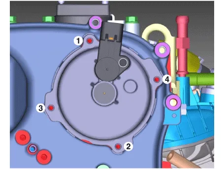
Install the E-CVVT cover.
|

| 8. |
Install the E-CVVT plug.
|
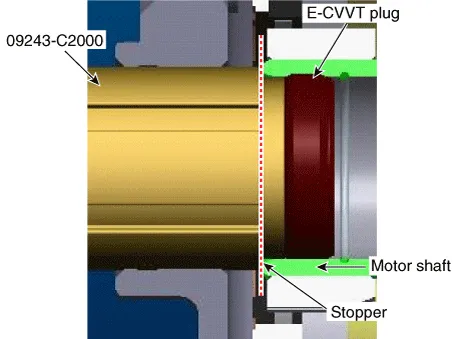
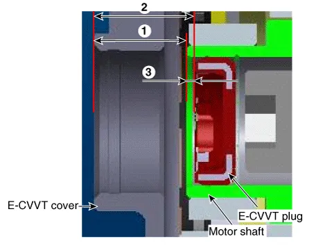
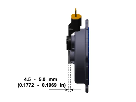
| 9. |
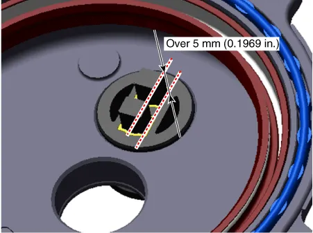
Inspect the pressed depth of E-CVVT plug.
|
| 10. |
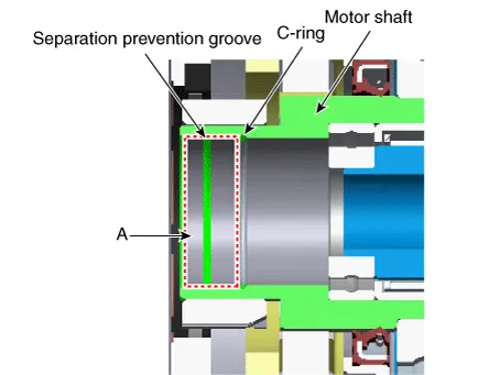
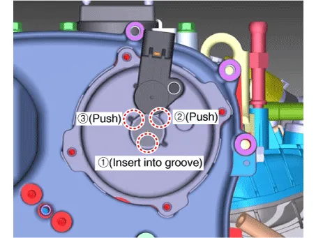
Insert the E-CVVT cover plug so that the protrusion (A) reach to E-CVVT cover groove correctly.
|
| 11. |
Install the other parts in the reverse order of removal. |
|


Other information:
Kia Stinger (CK) 2018-2023 Service Manual: Automatic Transmission Control System
Description and operation Description Automatic transmission control system relies on various measurements to determine the current control status and determine the necessary compensation values. These values are used to control the actuators and achieve the desired control output. Control System Composition Shift By Wire (SBW) System Composition ▶ Operating Principle – Instead of cable, the system uses electronic signals to shift between the P-R-N-D gears.Kia Stinger (CK) 2018-2023 Service Manual: Seat belt restraint system
For maximum restraint system protection, the seat belts must always be used whenever the vehicle is moving. A properly positioned shoulder belt should be positioned midway over your shoulder across your collarbone. Never allow children to ride in the front passenger seat. See child restraint system section for further discussion. WARNING - Twisted seat belt Make sure your seat belt is not twisted when worn.Categories
- Manuals Home
- Kia Stinger Owners Manual
- Kia Stinger Service Manual
- New on site
- Most important about car
