Kia Stinger CK: Transfer Assembly / Transfer Case Assembly
Components and components location
| Components Location |

| 1. Engine
2. Transmission 3. Rear differential 4. Rear propeller shaft |
5. Transfer
case 6. Front propeller shaft 7. Front differential |
Repair procedures
| Removal |
In case of replacing the controller (ECU) and transfer case due to changing characteristics of the frictional materials inside the transfer case, it is necessary to check and enter the calibration data.
|

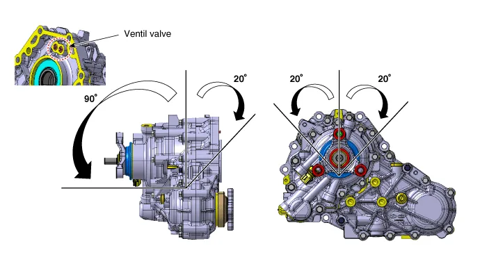
Cautions in handling the transfer case A. Preventing the oil leaking
|
| 1. |
Turn ignition switch OFF and disconnect the negative (-) battery cable. |
| 2. |
Remove the under cover. D 2.2 R VGT (Refer to Engine Mechanical System - "Engine Room Under cover") G 2.0 T-GDI THETA II (Refer to Engine Mechanical System - "Engine Room Under cover") G 3.3 T-GDI LAMBDA II (Refer to Engine Mechanical System - "Engine Room Under cover") |
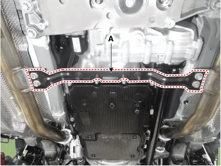
| 3. |
Remove the front muffler stay (A).
|
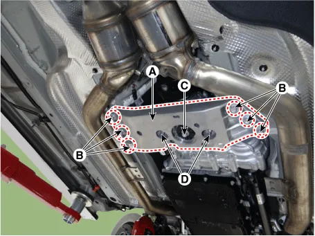
| 4. |
Remove the transmission cross member (A).
|
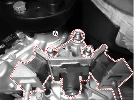
| 5. |
Remove the transmission cross member bracket (A).
|
| 6. |
Remove the propeller shaft. (Refer to Driveshaft and axle - "Propeller Shaft Assembly") |
| 7. |
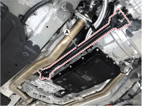
Remove the front propeller shaft (A).
|
| 8. |
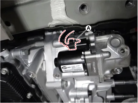
Disconnect the transfer actuator connector (A).
|
| 9. |
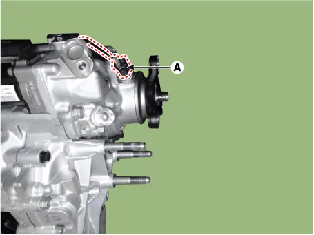
Disconnect the pressure sensor connector (A).
|
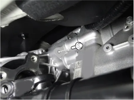
| 10. |
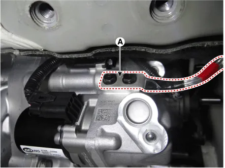
Loosen the bolts and then bracket (A).
|
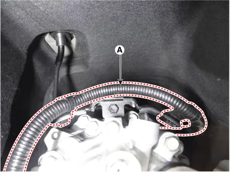
| 11. |
Remove the transfer wire ring (A).
|
| 12. |
Loosen the transfer bolts and then remove the transfer (A).
|

| Installation |
| 1. |
Install in the reverse order of removal.
|


Other information:
Kia Stinger (CK) 2018-2023 Service Manual: Curtain air bag
Curtain air bags are located along both sides of the roof rails above the front and rear doors. They are designed to help protect occupants in certain side impacts and to help prevent them from ejecting out of the vehicle as a result of a rollover, especially when the seatbelts are also in use. The curtain air bags are designed to deploy during certain side impact collisions, depending on the crash severity, angle, speed and point of impact.Kia Stinger (CK) 2018-2023 Service Manual: Seat belt warning
Driver’s seat belt warning As a reminder to the driver, the seat belt warning light will illuminate for approximately 6 seconds each time the engine start/stop button is in ON regardless of belt fastening and warning chime will sound for approximately 6 seconds each time the engine start/stop button is in ON when the belt is unfastened. If a driver continues not to fasten the seat belt and drive 9 km/h (5.Categories
- Manuals Home
- Kia Stinger Owners Manual
- Kia Stinger Service Manual
- New on site
- Most important about car
