Kia Stinger CK: Maintenance / Tires and wheels
Contents:
- Recommended cold tire inflation pressures
- Tire pressure
- Checking tire inflation pressure
- Tire rotation
- Wheel alignment and tire balance, Flat Spots
- Tire replacement
- Tire sidewall labeling
- Tire terminology and definitions
- All season tires, Summer tires
- Snow tires, Radial-ply tires
- Low aspect ratio tire
Tire care
For proper maintenance, safety, and maximum fuel economy, you must always maintain recommended tire inflation pressures and stay within the load limits and weight distribution recommended for your vehicle.
Recommended cold tire inflation pressures ➤
Tire pressure
Always observe the following:
- Check tire pressure when the tires are cold. (After vehicle has been parked for at least three hours or hasn't been driven more than 1.6 km (one mile) since startup.)
- Check the pressure of your spare tire each time you check the pressure of other tires.
- Never overload your vehicle. Be careful not to overload a vehicle luggage rack if your vehicle is equipped with one.
WARNING - Tire Inflation
Overinflation or underinflation can reduce tire life, adversely affect vehicle handling, and lead to sudden tire failure. This could result in loss of vehicle control and potential injury.
Checking tire inflation pressure ➤
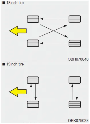
Tire rotation
To equalize tread wear, it is recommended that the tires be rotated every 10,000 km (6,000 miles) or sooner if irregular wear develops.
During rotation, check the tires for correct balance.
When rotating tires, check for uneven wear and damage. Abnormal wear is usually caused by incorrect tire pressure, improper wheel alignment, outof- balance wheels, severe braking or severe cornering. Look for bumps or bulges in the tread or side of tire. Replace the tire if you find either of these conditions. Replace the tire if fabric or cord is visible. After rotation, be sure to bring the front and rear tire pressures to specification and check lug nut tightness.
Refer to “Tire and wheels” in chapter 8.
Disc brake pads should be inspected for wear whenever tires are rotated.
Rotate radial tires that have an asymmetric tread pattern only from front to rear and not from right to left.
WARNING - Mixing tires
- Do not use the compact spare tire (if equipped) for tire rotation.
- Do not mix bias ply and radial ply tires under any circumstances. This may cause unusual handling characteristics.
Wheel alignment and tire balance, Flat Spots
Wheel alignment and tire balance
The wheels on your vehicle were aligned and balanced carefully at the factory to give you the longest tire life and best overall performance.
In most cases, you will not need to have your wheels aligned again. However, if you notice unusual tire wear or your vehicle pulling one way or the other, the alignment may need to be reset.
If you notice your vehicle vibrating when driving on a smooth road, your wheels may need to be rebalanced.
CAUTION - Wheel weight
Improper wheel weights can damage your vehicle's aluminum wheels. Use only approved wheel weights.
Flat Spots
If a vehicle is parked/not operated for a long period of time, tires may develop “flat spots”. Once the vehicle is driven again, these flat spots may cause a vibration which typically disappears gradually as the tires warm up and regain their original shape. To minimize tire flat spots developing during periods of extended storage, inflate the tires to the maximum pressure as indicated on the tire’s sidewall. When the vehicle is made ready to drive again, lower the tire pressure to the recommended levels as shown on the Tire and Loading Information label in the driver’s side center pillar for your vehicle (Refer to “Tire specification and pressure label” in chapter 8).
Tire replacement ➤
Tire sidewall labeling ➤
Tire terminology and definitions ➤
All season tires, Summer tires
All season tires
Kia specifies all season tires on some models to provide good performance for use all year round, including snowy and icy road conditions. All season tires are identified by ALL SEASON and/or M+S (Mud and Snow) on the tire sidewall. Snow tires have better snow traction than all season tires and may be more appropriate in some areas.
Summer tires
Kia specifies summer tires on some models to provide superior performance on dry roads. Summer tire performance is substantially reduced in snow and ice. Summer tires do not have the tire traction rating M+S (Mud and Snow) on the tire side wall. If you plan to operate your vehicle in snowy or icy conditions, Kia recommends the use of snow tires or all season tires on all four wheels.
WARNING
Do not use summer tires at temperatures below 7°C (45°F) or when driving on snow or ice. At temperatures below 7°C (45°F), summer tires can lose elasticity, and therefore traction and braking power as well. Change the tires on your vehicle to winter or all-weather tires of the same size as the standard tires of the vehicle. Both types of tires are identified by the M+S (Mud and Snow) marking. Using summer tires at very cold temperatures could cause cracks to form, thereby damaging the tires permanently.
Snow tires, Radial-ply tires
Snow tires
If you equip your car with snow tires, they should be the same size and have the same load capacity as the original tires. Snow tires should be installed on all four wheels; otherwise, poor handling may result.
Snow tires should carry 28 kPa (4 psi) more air pressure than the pressure recommended for the standard tires on the tire label on the driver's side of the center pillar, or up to the maximum pressure shown on the tire sidewall, whichever is less.
Do not drive faster than 120 km/h (75 mph) when your vehicle is equipped with snow tires.
Radial-ply tires
Radial-ply tires provide improved tread life, road hazard resistance and smoother high speed ride. The radial- ply tires used on this vehicle are of belted construction and are selected to complement the ride and handling characteristics of your vehicle.
Radial-ply tires have the same load carrying capacity as bias-ply or bias belted tires of the same size and use the same recommended inflation pressure. Mixing of radial-ply tires with bias-ply or bias belted tires is not recommended. Any combinations of radial-ply and bias-ply or bias belted tires when used on the same vehicle will seriously deteriorate vehicle handling. The best rule to follow is: identical radial-ply tires should always be used as a set of four.
Longer wearing tires can be more susceptible to irregular tread wear. It is very important to follow the tire rotation interval shown in this section to achieve the tread life potential of these tires. Cuts and punctures in radial-ply tires are repairable only in the tread area, because of sidewall flexing. Consult your tire dealer for radial-ply tire repairs.
Low aspect ratio tire
Low aspect ratio tires, whose aspect ratio is lower than 50, are provided for sporty looks.
Because the low aspect ratio tires are optimized for handling and braking, it may be more uncomfortable to ride in and there is more noise compare with normal tires.
CAUTION
Because the sidewall of the low aspect ratio tire is shorter than the normal, the wheel and tire of the low aspect ratio tire is easier to be damaged. So, follow the instructions below.
- When driving on a rough road or off road, drive cautiously because tires and wheels may be damaged. And after driving, inspect tires and wheels.
- When passing over a pothole, speed bump, manhole, or curb stone, drive slowly so that the tires and wheels are not damaged.
- If the tire is impacted, we recommend that you inspect the tire condition or contact an authorized Kia dealer.
- To prevent damage to the tire, inspect the tire condition and pressure every 3,000 km (1,900 miles).
- It is not easy to recognize the tire damage with your own eyes. But if there is the slightest hint of tire damage, even though you cannot see it, have the tire checked or replaced because the tire damage may cause air leakage from the tire.
- If the tire is damaged by driving on a rough road, off road, pothole, manhole, or curb stone, it will not be covered by the warranty.
- You can find out the tire information on the tire sidewall.


Other information:
Repair procedures Removal Door Mirror Turn Signal Lamp 1. Disconnect the negative (-) battery terminal. 2. Remove the outside rear view mirror. (Refer to Body - "Outside Rear View Mirror") 3. Remove mirror (A) to the direction as shown in the picture using (-) screw driver.Components and components location Component Location 1. Hood latch assembly Repair procedures Replacement 1. Remove the front bumper. (Refer to Front bumper - "Front bumper Assembly") 2. Remove the hood latch assembly (A) after loosening the mounting screw.Categories
- Manuals Home
- Kia Stinger Owners Manual
- Kia Stinger Service Manual
- Recommended cold tire inflation pressures
- Tire pressure
- Checking tire inflation pressure
- Tire rotation
- Wheel alignment and tire balance, Flat Spots
- Tire replacement
- Tire sidewall labeling
- Tire terminology and definitions
- All season tires, Summer tires
- Snow tires, Radial-ply tires
- Low aspect ratio tire
- New on site
- Most important about car
Contents
