
Kia Stinger CK: Front Suspension System / Sub Frame
Repair procedures
| Removal |
[2WD]
| 1. |
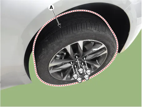
Remove wheel nuts, front wheel and tire (A) from hub.
|

| 2. |
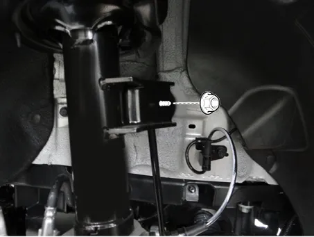
Loosen the nut and then separate the stabilizer link from the front shock absorber.
|
| 3. |
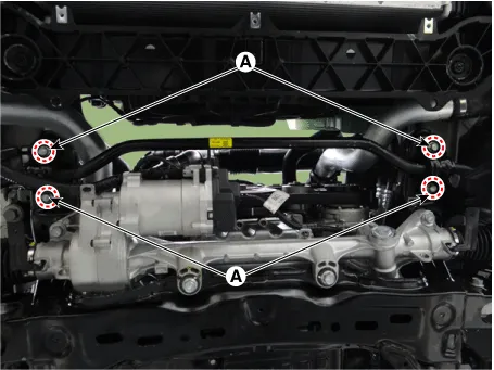
Loosen the bolts (A) and then remove the stabilizer bar.
|
| 4. |
Remove the engine room side cover. D 2.2 R VGT (Refer to Engine Mechanical System - "Engine Room Under cover") G 2.0 T-GDI THETA II (Refer to Engine Mechanical System - "Engine Room Under cover") G 3.3 T-GDI LAMBDA II (Refer to Engine Mechanical System - "Engine Room Under cover") |
| 5. |
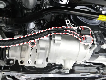
Disconnect the R-MDPS connector (A) and clip (B).
|
| 6. |
Loosen the shaft joint bolt (A) and then separate the shaft joint.
|
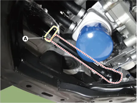
| 7. |
Disconnect the R-MDPS wiring clip (A) from the sub frame.
|
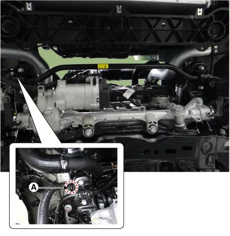
| 8. |
Remove the tie rod end nut.
|
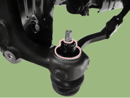
| 9. |
Remove the knuckle by using the ball joint remover (A).
|
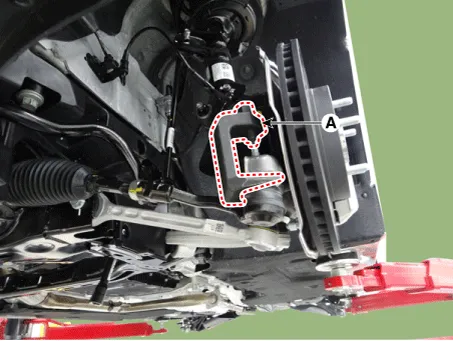
| 10. |
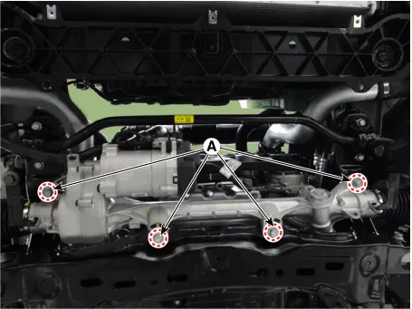
Loosen the gear box bolts (A) and then remove the gear box.
|
| 11. |
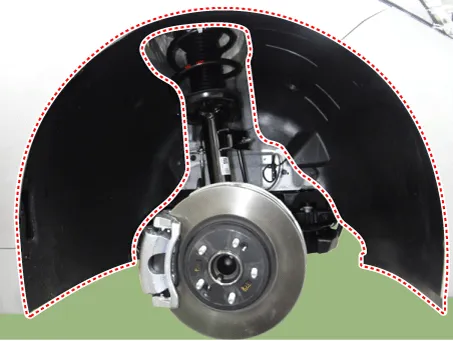
Remove the front wheel guard.
|
| 12. |
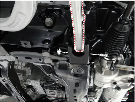
Remove the lateral arm.
|
| 13. |
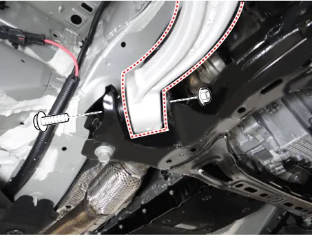
Loosen the compression arm bolt & nut from the subframe.
|
| 14. |
Remove the hood assembly. (Refer to Body - "Hood assembly") |
| 15. |
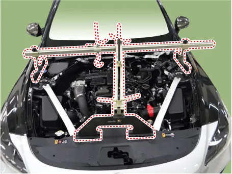
Assemble the engine support fixture on the engine room. (Refer to Special Service Tools - "Engine support fixture assembly drawing")
|
| 16. |
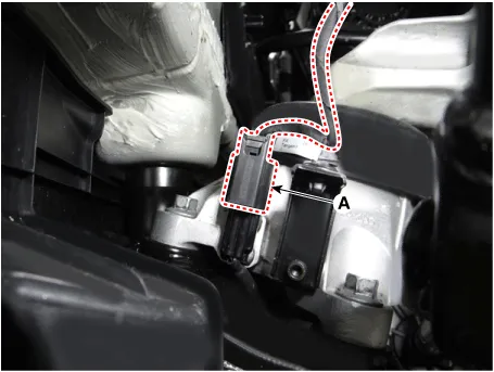
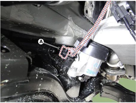
Disconnect the semi active engine mounting connector (A). [R 2.2] [LH]
[RH]
|
| 17. |
Loosen the intercooler inlet hose bolt. [R 2.2]
|

| 18. |
Loosen the engine mounting insulator nut (A).
[RH] [2.0 T-GDI THETA II, R 2.2]
[LH]
[3.3 T-GDI LAMBDA II]
|
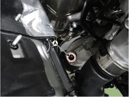
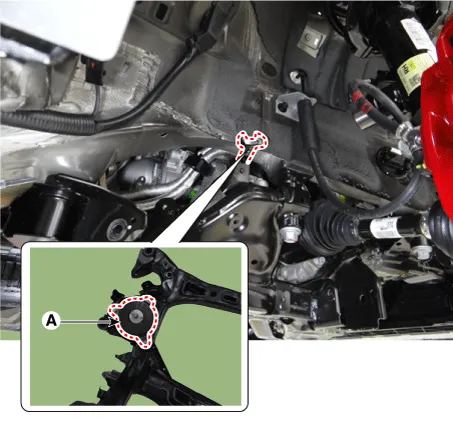
| 19. |
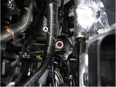
Remove the clip (A) from the sub frame. [3.3 T-GDI LAMBDA II]
|
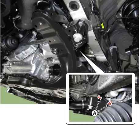
| 20. |
Loosen the bolts (A) and then remove the sub frame.
|
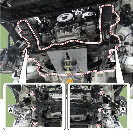
| 21. |
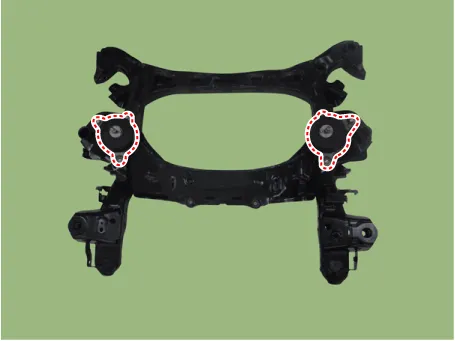
Remove the engine bracket from the sub frame.
|
| 22. |
Install in the reverse order of removal.
|
| 23. |
Check the front alignment. (Refer to Suspension System - "Alignment") |
[AWD]
| 1. |
Remove wheel nuts, front wheel and tire (A) from hub.
|
| 2. |
Remove the front wheel guard.
|
| 3. |
Remove the engine room side cover. D 2.2 R VGT (Refer to Engine Mechanical System - "Engine Room Under cover") G 2.0 T-GDI THETA II (Refer to Engine Mechanical System - "Engine Room Under cover") G 3.3 T-GDI LAMBDA II (Refer to Engine Mechanical System - "Engine Room Under cover") |
| 4. |
Remove the lateral arm.
|
| 5. |
Loosen the compression arm bolt & nut from the subframe.
|
| 6. |
Loosen the nut and then separate the stabilizer link from the front shock absorber.
|
| 7. |
Loosen the bolts (A) and then remove the stabilizer bar.
|
| 8. |
Disconnect the R-MDPS connector (A) and clip (B).
|
| 9. |
Loosen the shaft joint bolt (A) and then separate the shaft joint.
|
| 10. |
Disconnect the R-MDPS wiring clip (A) from the sub frame.
|
| 11. |
Loosen the gear box bolts (A) and then remove the gear box.
|
| 12. |
Remove the hood assembly. (Refer to Body - "Hood assembly") |
| 13. |
Assemble the engine support fixture on the engine room. (Refer to Special Service Tools - "Engine support fixture assembly drawing")
|
| 14. |
Disconnect the semi active engine mounting connector (A). [R 2.2] [LH]
[RH]
|
| 15. |
Loosen the intercooler inlet hose bolt. [R 2.2]
|
| 16. |
Loosen the engine mounting insulator nut (A).
[RH] [2.0 T-GDI THETA II, R 2.2]
[LH]
[3.3 T-GDI LAMBDA II]
|
| 17. |
Remove the clip (A) from the sub frame. [3.3 T-GDI LAMBDA II]
|
| 18. |
Loosen the bolts (A) and then remove the sub frame.
|
| 19. |
Remove the engine bracket from the sub frame.
|
| 20. |
Install in the reverse order of removal.
|
| 21. |
Check the front alignment. (Refer to Suspension System - "Alignment") |


Other information:
Kia Stinger (CK) 2018-2023 Service Manual: Vehicle load limit
Tire and loading information label The label located on the driver's door sill gives the original tire size, cold tire pressures recommended for your vehicle, the number of people that can be in your vehicle and vehicle capacity weight. Vehicle capacity weight: 410 kg (904 lbs.) Vehicle capacity weight is the maximum combined weight of occupants and cargo.Kia Stinger (CK) 2018-2023 Service Manual: Exhaust Gas Temperature Sensor (EGTS)
Specifications Specification Exhaust Gas Temperature Sensor (EGTS) #1, 2 ▷ Type : Thermistor type Temperature [°C (°F)] Resistance (kΩ) -40 (-40) 0.17 0 (-32) 0.201 100 (212) 0.276 200 (392) 0.Categories
- Manuals Home
- Kia Stinger Owners Manual
- Kia Stinger Service Manual
- New on site
- Most important about car
