Kia Stinger CK: Engine Control System / Accelerator Position Sensor (APS)
Specifications
| Specification |
|
Accelerator Position |
Output Voltage (V) [Vref = 5V] |
|
|
APS1 |
APS2 |
|
|
C.T |
0.7 - 0.8 |
0.33 - 0.43 |
|
W.O.T |
3.99 - 4.23 |
1.94 - 2.18 |
Description and operation
| Description |
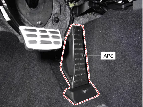
Installed on the accelerator pedal module, the Accelerator Position Sensor (APS) detects the rotation angle of the accelerator pedal. As the APS is one of the most important sensors in the engine control system, each of its two sensors has independent power and ground line. APS 2 monitors APS 1, and its output voltage is half that of APS 1. If the ratio of APS 1 and APS 2 is out of range (approximately 1/2), the diagnostic system judges it as abnormal.
Schematic diagrams
| Circuit Diagram |

Harness Connector

Repair procedures
| Inspection |
| 1. |
Connect the KDS on the Data Link Connector (DLC). |
| 2. |
TSwitch "ON" the ignition. |
| 3. |
Measure the output voltage of the APS 1 and 2 at C.T and W.O.T.
|
|||||||||||
| Removal |
| 1. |
Switch "OFF" the ignition and disconnect the negative (-) battery terminal. |
| 2. |
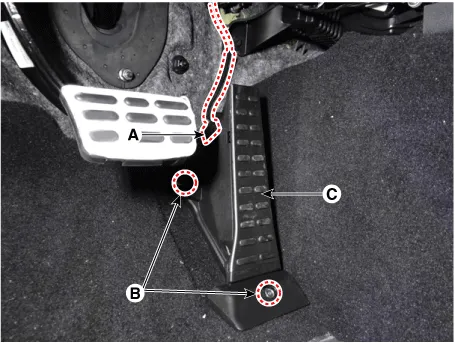
Disconnect the accelerator position sensor connector (A). |
| 3. |
Remove the accelerator position sensor (C) after loosening the mounting bolt and nut (B).
|
| Installation |
| 1. |
Install in the reverse order of removal. |


Other information:
Kia Stinger (CK) 2018-2023 Service Manual: Alternator
Specifications Specification ▷ 13.5V, 150A Item Specification Rated voltage 13.5V , 150A Speed in use 0 - 18,000 rpm Pin 1 Voltage regulator IC Regulator built in type Default regulated voltage (V) [COM terminal] 14.Kia Stinger (CK) 2018-2023 Service Manual: Overhead Console Lamp
Repair procedures Inspection 1. Remove the overhead console lamp assembly then check for continuity between terminals. If the continuity is not as specified, replace the map lamp switch. Removal 1. Disconnect the negative (-) battery terminal. 2.Categories
- Manuals Home
- Kia Stinger Owners Manual
- Kia Stinger Service Manual
- New on site
- Most important about car
