Kia Stinger CK: Engine Control System / Ambient Temperature Sensor (ATS)
Specifications
| Specification |
|
Temperature[⁰C(⁰F)] |
Resistance(kΩ) |
|
-40(-40) |
811.1 - 956.8 |
|
-20(-4) |
255.6 - 287.7 |
|
0(32) |
91.5 - 98.8 |
|
20(68) |
36.6 - 38.0 |
|
30(86) |
23.8 - 24.7 |
|
40(104) |
15.7 - 16.6 |
|
50(122) |
10.6 - 11.3 |
|
60(140) |
7.2 - 7.9 |
|
80(176) |
3.6 - 4.0 |
Description and operation
| Description |
Installed on the front-end module, the Ambient Temperature Sensor (ATS) senses the ambient temperature. ECM receives the intake air temperature and ambient air temperature at the same time to precisely control the intake air quantity supplied through the turbocharger. The electrical resistance of the thermistor decreases as the temperature increases, and vice versa. This sensor has a Negative Temperature Coefficient (NTC) and its resistance is in inverse proportion to the temperature.
Schematic diagrams
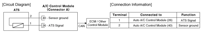
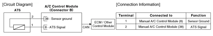
| Circuit Diagram |
| Auto A/C |
| Manual A/C |
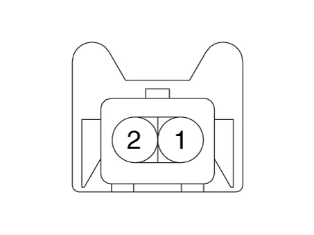
Harness Connector
Repair procedures
| Inspection |
| 1. |
Switch "OFF" the ignition. |
| 2. |
Disconnect the ATS connector. |
| 3. |
Measure resistance between the ATS terminals 1 and 2. |
| 4. |
Check that the resistance is within the specification.
|
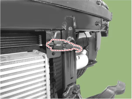
| Removal |
| 1. |
Switch "OFF" the ignition and disconnect the negative (-) battery terminal. |
| 2. |
Remove the front engine room under cover. (Refer to Engjne Mechanical System - "Engine Room Under Cover") |
| 3. |
Disconnect the connector (A) and then remove the ambient temperature sensor (B).
|

| Installation |
Note that internal damage may occur when the component is dropped. If the component has been dropped, inspect before installing. |

| 1. |
Install in the reverse order of removal. |


Other information:
Kia Stinger (CK) 2018-2023 Service Manual: Tail Gate Assembly
Components and components location Components Location 1. Tailgate assembly Repair procedures Replacement Wear gloves to protect hands from injury. When removing and installing the tail gate, an assistant is needed.Kia Stinger (CK) 2018-2023 Service Manual: Crash Pad Lower Panel
Components and components location Component Location 1. Crash pad lower panel Repair procedures Replacement Put on gloves to protect your hands. • Use a plastic panel removal tool to remove interior trim pieces without marring the surface.Categories
- Manuals Home
- Kia Stinger Owners Manual
- Kia Stinger Service Manual
- New on site
- Most important about car
