Kia Stinger CK: Tail Gate / Tail Gate Assembly
Components and components location
| Components Location |

| 1. Tailgate assembly |
Repair procedures
| Replacement |
Wear gloves to protect hands from injury. |

When removing and installing the tail gate, an assistant is needed. |

| 1. |
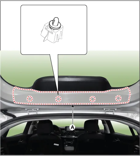
Remove the tailgate upper trim (A).
|
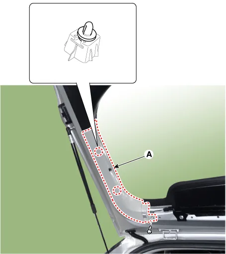
| 2. |
Remove the tailgate side trim (A) after loosening the mounting screw.
|
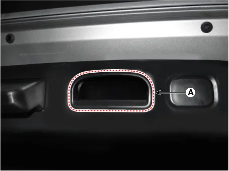
| 3. |
Remove the tailgate inside full handle cap (A) by using a remover.
|
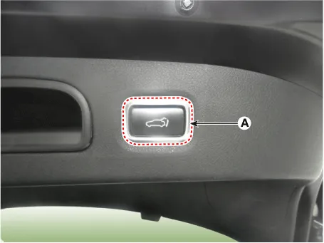
| 4. |
Separate the smart tailgate inner switch (A).
|
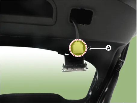
| 5. |
Remove the smart tailgate inner switch after disconnecting the connector (A).
|
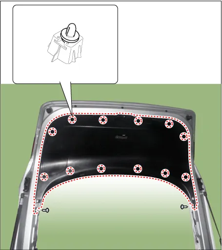
| 6. |
Remove the tailgate trim (A) after loosening the mounting screws.
|
| 7. |
Disconnect the high mounted stop lamp connector (A).
|

| 8. |
Remove the high mounted stop lamp (A) after loosening the mounting bolts.
|

| 9. |
Separate the extension wiring harness (B) after disconnecting the connectors (A).
|

| 10. |
Using a screwdriver, separate the both ends of the tailgate lifter (B) after removing the socket clips (A).
|

| 11. |
Remove the tailgate assembly (A) after loosening the mounting bolts.
|

| 12. |
Install in the reverse order of removal.
|


Other information:
Kia Stinger (CK) 2018-2023 Service Manual: AVN System
Components and components location Component Location 1 . AVN head unit 2. AVN front monitor 3. External amplifier 4. Multimedia jack 5 . Steering wheel remote control(SWRC) 6 . Hands-free mic 7 . Roof antenna(Radio + GPS + DAB) Description and operation Description AVN system The AVN system simplifies system manipulation and by unifying the vehicle information and user information displays, improves information search and operation experience.Kia Stinger (CK) 2018-2023 Service Manual: Knee Airbag (KAB) Module
Description and operation Description Installed inside the crash pad, the knee airbag (KAB) protects the driver in the event of a frontal crash. The SRSCM determines if and when to deploy the KAB. Never attempt to measure the circuit resistance of the airbag module (squib) even if you are using a specified tester.Categories
- Manuals Home
- Kia Stinger Owners Manual
- Kia Stinger Service Manual
- New on site
- Most important about car
