Kia Stinger CK: ISG (Idle Stop & Go) System / DC/DC Converter
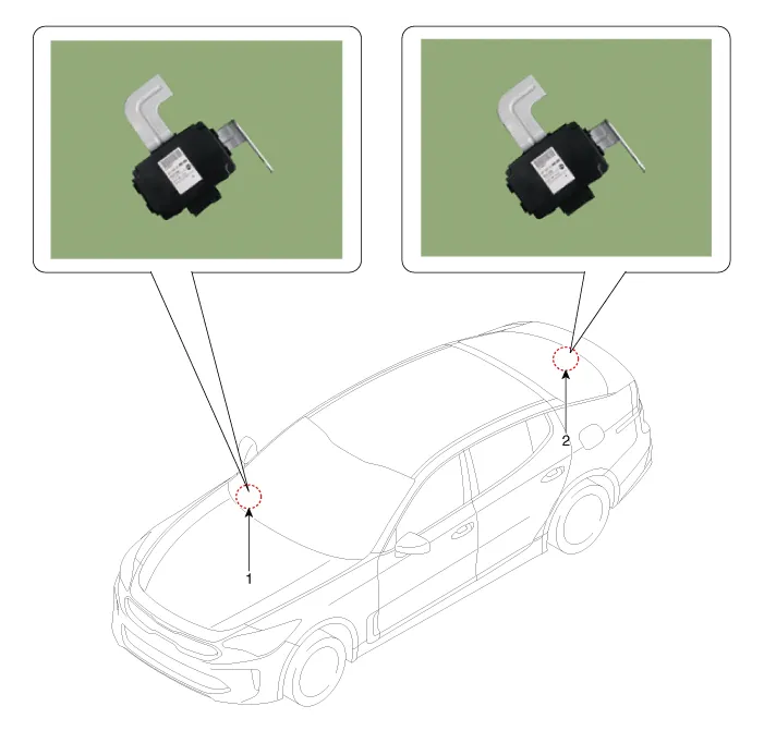
Components and components location
| Components Location |
Schematic diagrams
| Circuit Diagram |
| [200W] |
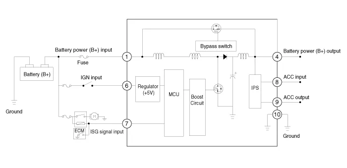
| [400W] |

| Terminal Function |
| [200W] |

|
PIn. |
Description |
PIn. |
Description |
|
1 |
Battery power (B+) input |
7 |
ISG signal input |
|
2 |
- |
8 |
ACC input |
|
3 |
- |
9 |
ACC output |
|
4 |
Battery power (B+) output |
10 |
Ground |
|
5 |
- |
11 |
- |
|
6 |
IGN1 input |
|
|
| [400W] |

|
PIn. |
Description |
PIn. |
Description |
|
1 |
Battery power (B+) input |
7 |
Battery power (B+) input |
|
2 |
- |
8 |
Battery power (B+) output |
|
3 |
Battery power (B+) output |
9 |
Battery power (B+) output |
|
4 |
Ground |
10 |
Ground |
|
5 |
IGN1 input |
11 |
ACC output |
|
6 |
ISG signal input |
12 |
ACC input |
Repair procedures
| Removal |
| [200W] |
| 1. |
Switch "OFF" the ignition and disconnect the negative (-) battery terminal. |
| 2. |
Remove the glove box housing. (Refer to Body (Interior and Exterior) - "Glove Box Housing") |
| 3. |
Remove the [RH] side air bant duct (A) after loosening the mounting screw.
|
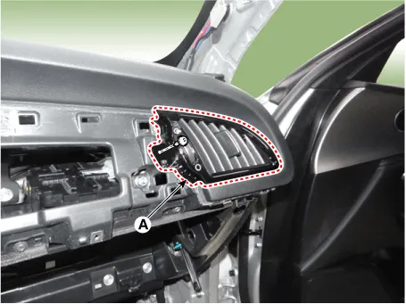
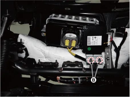
| 4. |
Remove the DC/DC converter after loosening the mounting bolt (A) and nut(B).
|
| [400W] |
| 1. |
Switch "OFF" the ignition and disconnect the negative (-) battery terminal. |
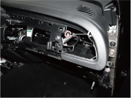
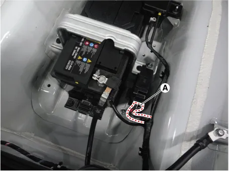
| 2. |
Disconnect the DC/DC converter connector (A).
|
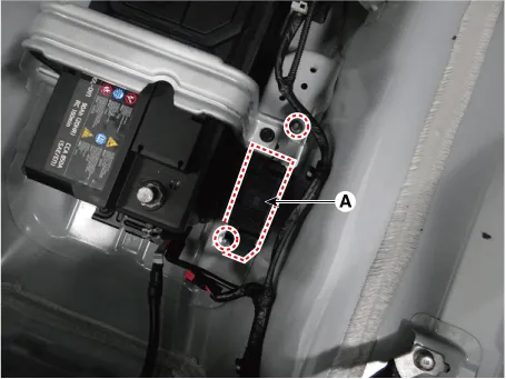
| 3. |
Remove the DC/DC converter (A) after loosening the mounting nuts.
|
| Installation |
After reconnecting the battery negative cable, ISG function does not operates until the system is stabilized, about 4 hours. If disconnecting the negative (-) battery cable from the battery during repair work for the vehicle equipped with AMS function, Battery sensor recalibration procedure should be performed after finishing the repair work. |

| 1. |
Install in the reverse order of removal. |


Other information:
Kia Stinger (CK) 2018-2023 Service Manual: Vehicle stability management (VSM)
This system provides further enhancements to vehicle stability and steering responses when a vehicle is driving on a slippery road or a vehicle detects changes in coefficient of friction between right wheels and left wheels when braking. WARNING - Tire/ Wheel size When replacing tires and wheels, make sure they are the same size as the original tires and wheels installed.Service data Service Data Items Specification Hood Type Rear hinged, gas lifter type Front Door Structure Front hinged, full door structure Regulator system Wire drum type Locking system Pin-fork system Rear Door Structure Front hinged, full door structure Regulator system Wire drum type Locking system Pin-fork system Trunk Lid Type Front hinged, power trunk lid type (option ) Seat Belts Front 3-point type with Emergency Locking Retractor (E.Categories
- Manuals Home
- Kia Stinger Owners Manual
- Kia Stinger Service Manual
- New on site
- Most important about car
