Kia Stinger CK: Engine Control System / Accelerator Position Sensor (APS)
Specifications
| Specification |
|
Accelerator Position |
Output Voltage (V) [Vref = 5V] |
|
|
APS1 |
APS2 |
|
|
C.T |
0.7 - 0.8 |
0.33 - 0.43 |
|
W.O.T |
3.99 - 4.23 |
1.94 - 2.18 |
Description and operation
| Description |
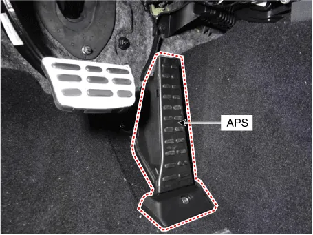
Installed on the accelerator pedal module, the Accelerator Position Sensor (APS) detects the rotation angle of the accelerator pedal. As the APS is one of the most important sensors in the engine control system, each of its two sensors has independent power and ground line. APS 2 monitors APS 1, and its output voltage is half that of APS 1. If the ratio of APS 1 and APS 2 is out of range (approximately 1/2), the diagnostic system judges it as abnormal.
Schematic diagrams
| Circuit Diagram |

Harness Connector

Repair procedures
| Inspection |
| 1. |
Connect the KDS on the Data Link Connector (DLC). |
| 2. |
TSwitch "ON" the ignition. |
| 3. |
Measure the output voltage of the APS 1 and 2 at C.T and W.O.T.
|
|||||||||||
| Removal |
| 1. |
Switch "OFF" the ignition and disconnect the negative (-) battery terminal. |
| 2. |
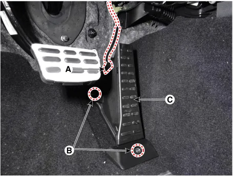
Disconnect the accelerator position sensor connector (A). |
| 3. |
Remove the accelerator position sensor (C) after loosening the mounting bolt and nut (B).
|
| Installation |
| 1. |
Install in the reverse order of removal. |


Other information:
Kia Stinger (CK) 2018-2023 Service Manual: How does the air bag system operate?
Air bags are activated (able to inflate if necessary) only when the Engine Start/Stop button is turned to the ON or engine is running. The appropriate air bags inflate instantly in the event of a serious frontal collision or side collision in order to help protect the occupants from serious physical injury. There is no single speed at which the air bags will inflate.Kia Stinger (CK) 2018-2023 Service Manual: Electric Waste Gate Actuator (EWGA)
Description and operation Desrcription Installed on the turbocharger, the Electric Waste Gate Actuator (EWGA) operates the vane in the Waste Gate Turbocharger (WGT) and regulates the compressed air amount based on the PWM signal from the ECM. This actuator consists of a DC motor which actuates the vane, a 2-step gear which increases torque of the DC motor, a position sensor which detects status of the vane, and an electric control unit which drives the DC motor.Categories
- Manuals Home
- Kia Stinger Owners Manual
- Kia Stinger Service Manual
- New on site
- Most important about car
