Kia Stinger CK: Driving your vehicle / Cruise control system
Contents:
- To set cruise control speed
- To increase cruise control set speed
- To decrease the cruising speed
- To cancel cruise control, do one of the following
- To resume cruising speed at more than approximately 30 km/h (20 mph)
- To turn cruise control off, do one of the following

The cruise control system allows you to program the vehicle to maintain a constant speed without depressing the accelerator pedal.
This system is designed to function above approximately 30 km/h (20 mph ).
- If the cruise control is left on, (cruise indicator light is illuminated), the cruise control can be switched on accidentally. Keep the cruise control system off when the cruise control is not in use, to avoid inadvertently setting a speed.
- Use the cruise control system only when traveling on open highways in good weather.
- Do not use the cruise control when it may not be safe to keep the vehicle at a constant speed, for instance, driving in heavy or varying traffic, or on slippery (rainy, icy or snow- covered) or winding roads or over 6% up-hill or down-hill roads.
- Pay particular attention to the driving conditions whenever using the cruise control system.
- Be careful when driving downhill using the cruise control system, which may increase the vehicle speed.
✽ NOTICE
- During normal cruise control operation, when the SET switch is activated or reactivated after applying the brakes, the cruise control will activate after approximately 3 seconds. This delay is normal.
- To activate cruise control, depress the brake pedal at least once after turning the ignition switch to the ON position or starting the engine.
WARNING - Misuse of Cruise Control
Do not use cruise control if the traffic situation does not allow you to drive safely at a constant speed and with sufficient distance to the vehicle in front.
To set cruise control speed

1. Press the CRUISE button on the steering wheel to turn the system on. The CRUISE indicator light in the instrument cluster will illuminate.
2. Accelerate to the desired speed, which must be more than 30 km/h (20 mph).

3. Move the lever down (to SET-), and release it at the desired speed.The cruise indicator and set speed on the LCD screen will illuminate. Release the accelerator at the same time. The desired speed will automatically be maintained.
On a steep grade, the vehicle may slow down slightly when driving uphill or speed up slightly while going downhill.
To increase cruise control set speed
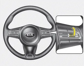
Follow either of these procedures:
- Move the lever up (to RES+) and hold it.Your vehicle will accelerate. Release the lever at the speed you want.
- Move the lever up (to RES+) and release it immediately. The cruising speed will increase by 1 km/h (1.0 mph) each time the lever is operated in this manner.
To decrease the cruising speed
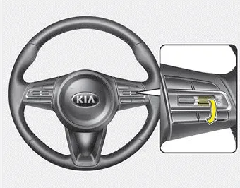
Follow either of these procedures:
- Move the lever down (to SET-) and hold it. Your vehicle will gradually slow down. Release the lever at the speed you want to maintain.
- Move the lever down (to SET-) and release it immediately. The cruising speed will decrease by 1 km/h (1.0 mph) each time the lever is operated in this manner.
To temporarily accelerate with the cruise control on:
If you want to speed up temporarily when the cruise control is on, depress the accelerator pedal. Increased speed will not interfere with the cruise control operation or change the set speed.
To return to the set speed, take your foot off the accelerator.
To cancel cruise control, do one of the following

- Depress the brake pedal.
- Shift into N (Neutral) with an Automatic transmission.
- Press the CANCEL switch.
- Decrease the vehicle speed lower than the set speed by 20 km/h (12 mph).
- Decrease the vehicle speed to less than approximately 25 km/h (15 mph).
Each of these actions will cancel cruise control operation (The set speed on the LCD will disappear and the CRUISE indicator will illuminate continuously.), but it will not turn the system off. If you wish to resume cruise control operation, move the lever up (to RES+). You will return to your previously preset speed.
To resume cruising speed at more than approximately 30 km/h (20 mph)

If any method other than the CRUISE ON-OFF switch was used to cancel cruising speed and the system is still activated, the most recent set speed will automatically resume when you move the lever up.
It will not resume, however, if the vehicle speed has dropped below approximately 30 km/h (20 mph).
To turn cruise control off, do one of the following

- Press the CRUISE button (the CRUISE indicator light in the instrument cluster will go off).
- Turn the ignition off.
Both of these actions will cancel the cruise control operation. If you want to resume the cruise control operation, repeat the steps provided in “To set cruise control speed” on the previous page.


Other information:
Kia Stinger (CK) 2018-2023 Owner's Manual: Rear Transverse Trim
Components and components location Component Location 1. Rear pillar trim Repair procedures Replacement Put on gloves to protect your hands. • Use a plastic panel removal tool to remove interior trim pieces without marring the surface.Kia Stinger (CK) 2018-2023 Owner's Manual: Smart Key Diagnostic
Repair procedures Inspection 1. In the body electrical system, failure can be quickly diagnosed by using the vehicle diagnostic system (KDS). The diagnostic system (KDS) provides the following information. (1) Self diagnosis : Checking failure and code number (DTC). (2) Current data : Checking the system input/output data state.Categories
- Manuals Home
- Kia Stinger Owners Manual
- Kia Stinger Service Manual
- To set cruise control speed
- To increase cruise control set speed
- To decrease the cruising speed
- To cancel cruise control, do one of the following
- To resume cruising speed at more than approximately 30 km/h (20 mph)
- To turn cruise control off, do one of the following
- New on site
- Most important about car
Contents
