Kia Stinger CK: Driving your vehicle / Smart cruise control with stop & go system
Contents:
- Speed setting (Smart cruise control system)
- Vehicle to vehicle distance setting (Smart cruise control system)
- When the lane ahead is clear
- To adjust the sensitivity of smart cruise control system
- To convert to cruise control mode
- Limitations of the system
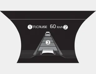
➀ Cruise indicator
➁ Set speed
➂ Vehicle-to-vehicle distance
The smart cruise control system allows you to program the vehicle to maintain a constant speed and a predetermined distance to the vehicle ahead without depressing the accelerator or brake pedal.
WARNING - Smart cruise control system Inadvertent Activation
If the smart cruise control system is left on (CRUISE indicator in the instrument cluster illuminated), it can be activated inadvertently. Keep the smart cruise control system off (CRUISE indicator off) when the smart cruise control system is not in use to avoid setting a speed which the driver is not aware of.
WARNING - Smart cruise control system Limitations
- The smart cruise control system is a supplemental system and is not a substitute for safe driving practices. It is the responsibility of the driver to always check the speed and distance to the vehicle ahead.
- Use the smart cruise control system only when traveling on open highways in good weather.
- Do not use the smart cruise control when it may not be safe to keep the
car at a constant speed. For instance.
- Highway interchange and tollgate
- Road surrounded by multiple steel constructions (subway construction, steel tunnel, etc)
- Parking lot
- Lanes beside guard rail on a road
- Slippery road with rain, ice, or snow
- Abrupt curved road
- Steep hills
- Windy roads
- Off roads
- Roads under construction
- Rumble strip
- When driving near crash barriers
- When driving on a sharp curve
- When the vehicle sensing ability decreases due to vehicle modification resulting level difference of the vehicle's front and rear
- When driving in heavy traffic or when traffic conditions make it difficult to drive at a constant speed - Limited visibility (rain, snow, smog, etc.)
- The smart cruise control system cannot recognize a stopped vehicle, pedestrians or an oncoming vehicle. Always look ahead cautiously to prevent unexpected and sudden situations from occurring.
- Pay particular attention to the driving conditions whenever using the smart cruise control system.
- Be careful when driving downhill using the SCC.
- Cruise function should not be used when the vehicle is being towed to prevent any damage.
- Always set the vehicle speed under the speed limit.
- Always pay continuous attention to road and driving even when the smart cruise control system is being operated.
Smart cruise control switch
O : Cancels cruise control operation.
 : Turns cruise control system on
or off.
: Turns cruise control system on
or off.
RES + : Resumes or increases cruise control speed.
SET - : Sets or decreases cruise control speed.
 : Sets vehicle-to-vehicle distance
Speed setting (Smart cruise control system) ➤
Vehicle to vehicle distance setting (Smart cruise control system) ➤
When the lane ahead is clear ➤
To adjust the sensitivity of smart cruise control system
The sensitivity of vehicle speed when following the front vehicle to maintain the set distance can be adjusted. Go to the User Settings Mode (Driver Assistance) and select SCC (Smart Cruise Control). You may select one of the three stages you prefer.
• Slow:
Vehicle speed to the vehicle ahead to maintain the set distance is slower than normal speed.
• Normal:
Vehicle speed to the vehicle ahead to maintain the set distance is normal
• Fast:
Vehicle speed to the vehicle ahead to maintain the set distance is faster than normal speed.
✽ NOTICE
The system remembers the last selected mode.
To convert to cruise control mode
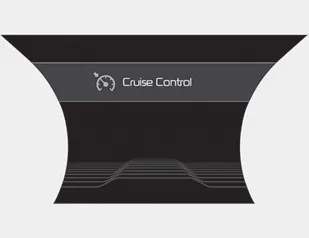
The driver may choose to only use the cruise control mode (speed control function) by doing as follows:
1.Turn the smart cruise control system on (the cruise indicator light will be on but the system will not be activated).
2.Push the distance to distance switch for more than 2 seconds.
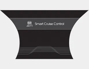
3.Choose between "Smart cruise control (SCC) mode" and "Cruise control (CC) mode".
When using the cruise control mode, you must manually assess the distance to other vehicles as the system will not automatically brake to slow down for other vehicles.
When the system is canceled using the CRUISE button or the CRUISE button is used after the engine is turned on, the Smart Cruise Control mode will turn on.
WARNING
When using the cruise control mode, you must manually assess the distance to other vehicles as the system will not automatically brake to slow down for other vehicles.
Limitations of the system ➤


Other information:
Kia Stinger (CK) 2018-2023 Owner's Manual: Fuse/relay panel description
■ Driver’s side fuse panel ■ Engine compartment fuse panel ■ Rear fuse box panel ■ Battery box fuse panel Inside the fuse/relay panel covers, you can find the fuse/relay label describing fuse/relay name and capacity. ✽ NOTICE Not all fuse panel descriptions in this manual may be applicable to your vehicle. It is accurate at the time of printing.Kia Stinger (CK) 2018-2023 Owner's Manual: Rear Shock Absorber
Components and components location Components 1. Lock nut 2. Rear insulator 3. Bumper stopper 4. Dust cover 5. Shock absorber Repair procedures Removal 1. Remove wheel nuts, rear wheel and tire (A) from hub. Tightening torque : 107.9 - 127.Categories
- Manuals Home
- Kia Stinger Owners Manual
- Kia Stinger Service Manual
- Speed setting (Smart cruise control system)
- Vehicle to vehicle distance setting (Smart cruise control system)
- When the lane ahead is clear
- To adjust the sensitivity of smart cruise control system
- To convert to cruise control mode
- Limitations of the system
- New on site
- Most important about car
Contents
