Kia Stinger CK: Brake system / Parking brake – Foot type
Contents:
Applying the parking brake
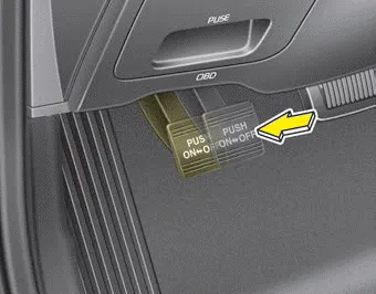
To engage the parking brake, first apply the foot brake and then depress the parking brake pedal down as far as possible.
CAUTION - Parking brake
Driving with the parking brake applied will cause excessive brake pad (or lining) and brake rotor wear.
Releasing the parking brake
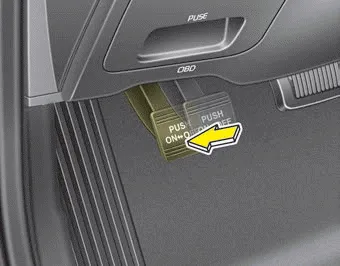
To release the parking brake, depress the parking brake pedal a second time while applying the foot brake. The pedal will automatically extend to the fully released position.
WARNING - Parking brake use
- Never allow a passenger to touch the parking brake. If the parking brake is released unintentionally, serious injury may occur.
- All vehicles should always have the parking brake fully engaged when parked to avoid inadvertent movement of the vehicles which can injure occupants or pedestrians.

Check the brake warning light by turning the ignition switch ON (do not start the engine). This light will be illuminated when the parking brake is applied with the ignition switch in the START or ON position.
Before driving, be sure the parking brake is fully released and the brake warning light is off.
If the brake warning light remains on after the parking brake is released while the engine is running, there may be a malfunction in the brake system. Immediate attention is necessary.
If at all possible, cease driving the vehicle immediately. If that is not possible, use extreme caution while operating the vehicle and only continue to drive the vehicle until you can reach a safe location or repair shop.


Other information:
Kia Stinger (CK) 2018-2023 Owner's Manual: Tire terminology and definitions
Air Pressure: The amount of air inside the tire pressing outward on the tire. Air pressure is expressed in kilopascal (kPa) or pounds per square inch (psi). Accessory Weight: This means the combined weight of optional accessories. Some examples of optional accessories are, automatic transaxle, power seats, and air conditioning. Aspect Ratio: The relationship of a tire's height to its width.Components and components location Component Location 1. Sunvisor 2. Repair procedures Replacement Put on gloves to protect your hands. • Use a plastic panel removal tool to remove interior trim pieces without marring the surface.Categories
- Manuals Home
- Kia Stinger Owners Manual
- Kia Stinger Service Manual
- New on site
- Most important about car
Contents
