Kia Stinger CK: Brake system / Electronic stability control (ESC)
Contents:
The Electronic Stability control (ESC) system is designed to stabilize the vehicle during cornering maneuvers. ESC checks where you are steering and where the vehicle is actually going. ESC applies the brakes on individual wheels and intervenes with the engine management system to stabilize the vehicle.
Electronic stability control (ESC) will not prevent accidents. Excessive speed in turns, abrupt maneuvers and hydroplaning on wet surfaces can still result in serious accidents. Only a safe and attentive driver can prevent accidents by avoiding maneuvers that cause the vehicle to lose traction. Even with ESC installed, always follow all the normal precautions for driving - including driving at safe speeds for the conditions.
WARNING
For maximum protection, always wear your seat belt. No system, no matter how advanced, can compensate for all driver error and/or driving conditions. Always drive responsibly.
The Electronic Stability Control (ESC) system is an electronic system designed to help the driver maintain vehicle control under adverse conditions. It is not a substitute for safe driving practices. Factors including speed, road conditions and driver steering input can all affect whether ESC will be effective in preventing a loss of control. It is still your responsibility to drive and corner at reasonable speeds and to leave a sufficient margin of safety.
When you apply your brakes under conditions which may lock the wheels, you may hear a “tik-tik’’ sound from the brakes, or feel a corresponding sensation in the brake pedal. This is normal and it means your ESC is active.
✽ NOTICE
A click sound may be heard in the engine compartment when the vehicle begins to move after the engine is started. These conditions are normal and indicate that the Electronic Stability Control System is functioning properly.
ESC operation
ESC ON condition

- When the ignition is turned ON, ESC and ESC OFF indicator lights illuminate for approximately 3 seconds, then ESC is turned on.
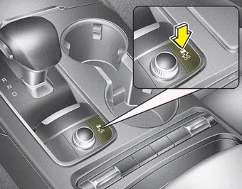
- Press the ESC OFF button for at least half a second after turning the ignition ON to turn ESC off. (ESC OFF indicator will illuminate). To turn the ESC on, press the ESC OFF button (ESC OFF indicator light will go off).
- When starting the engine, you may hear a slight ticking sound. This is the ESC performing an automatic system self-check and does not indicate a problem.
When operating

When the ESC is in operation, the ESC indicator light blinks.
- When the Electronic Stability Control is operating properly, you can feel a slight pulsation in the vehicle. This is only the effect of brake control and indicates nothing unusual.
- When moving out of the mud or driving on a slippery road, pressing the accelerator pedal may not cause the engine rpm (revolutions per minute) to increase.
ESC operation off
ESC OFF state

There are 2 types of ESC OFF states; Traction Control disabled and Traction & Stability Control disabled.
If the ignition is turned off when ESC is off, ESC remains off. Upon restarting the engine, the ESC will automatically turn on again.
• ESC off state 1
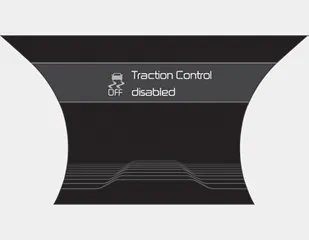
To cancel ESC operation, press the ESC OFF button (ESC OFF
 ) shortly (ESC OFF indicator light (ESC
OFF
) shortly (ESC OFF indicator light (ESC
OFF
 ) illuminates). At this state, the
engine control function does not operate. It means the traction control function
does not operate. Brake control function only operates.
) illuminates). At this state, the
engine control function does not operate. It means the traction control function
does not operate. Brake control function only operates.
• ESC off state 2
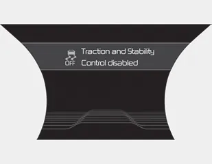
To cancel ESC operation, press the ESC OFF button (ESC OFF
 ) for more than 3 seconds. ESC OFF indicator
light (ESC OFF
) for more than 3 seconds. ESC OFF indicator
light (ESC OFF
 ) illuminates and ESC
OFF warning chime will sound. At this state, the engine control function and brake
control function do not operate. It means the car stability control function does
not operate any more.
) illuminates and ESC
OFF warning chime will sound. At this state, the engine control function and brake
control function do not operate. It means the car stability control function does
not operate any more.
Indicator light
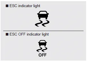
When ignition switch is turned to ON, the indicator light illuminates, then goes off if the ESC system is operating normally.
The ESC indicator light blinks whenever ESC is operating or illuminates when ESC fails to operate.
The ESC OFF indicator light comes on when the ESC is turned off with the button.
WARNING - Electronic stability control
Drive carefully even though your vehicle has Electronic Stability Control. It can only assist you in maintaining control under certain circumstances.
ESC OFF usage
When driving
- ESC should be turned on for daily driving whenever possible.
- To turn ESC off while driving, press the ESC OFF button while driving on a flat road surface.
WARNING - Operating ESC
Never press the ESC OFF button while ESC is operating (ESC indicator light blinks). If ESC is turned off while ESC is operating, the vehicle may slip out of control.
✽ NOTICE
- When operating the vehicle on a dynamometer, ensure that the ESC is turned off (ESC OFF light illuminated). If the ESC is left on, it may prevent the vehicle speed from increasing, and result in false diagnosis.
- Turning the ESC off does not affect ABS or brake system operation.


Other information:
Kia Stinger (CK) 2018-2023 Owner's Manual: Wiper blades
Blade inspection Commercial hot waxes applied by automatic car washes have been known to make the windshield difficult to clean. Contamination of either the windshield or the wiper blades with foreign matter can reduce the effectiveness of the windshield wipers. Common sources of contamination are insects, tree sap, and hot wax treatments used by some commercial car washes.Kia Stinger (CK) 2018-2023 Owner's Manual: Accelerator Position Sensor (APS)
Specifications Specification Accelerator Position Output Voltage (V) [Vref = 5V] APS1 APS2 C.T 0.7 - 0.8 0.33 - 0.43 W.O.T 3.99 - 4.23 1.94 - 2.18 Description and operation Description Installed on the accelerator pedal module, the Accelerator Position Sensor (APS) detects the rotation angle of the accelerator pedal.Categories
- Manuals Home
- Kia Stinger Owners Manual
- Kia Stinger Service Manual
- New on site
- Most important about car
Contents
