Kia Stinger CK: Maintenance / Scheduled maintenance service
Contents:
Follow the Normal Maintenance Schedule if the vehicle is usually operated where none of the following conditions apply. If any of the following conditions apply, follow the Maintenance Under Severe Usage Conditions.
- Repeated driving short distance of less than 8 km (5 miles) in normal temperature or less than 16 km (10 miles) in freezing temperature
- Extensive engine idling or low speed driving for long distances
- Driving on rough, dusty, muddy, unpaved, graveled or salt-spread roads
- Driving in areas using salt or other corrosive materials or in very cold weather
- Driving in heavy dust condition
- Driving in heavy traffic area
- Driving on uphill, downhill, or mountain road repeatedly
- Towing a trailer or using a camper, or roof rack
- Driving as a patrol car, taxi, other commercial use of vehicle towing
- Driving over 170 km/h (106 mph)
- Frequently driving in stop-and-go condition
If your vehicle is operated under the above conditions, you should inspect, replace or refill more frequently than the following Normal Maintenance Schedule. After 120 months or 150,000 miles continue to follow the prescribed maintenance intervals.
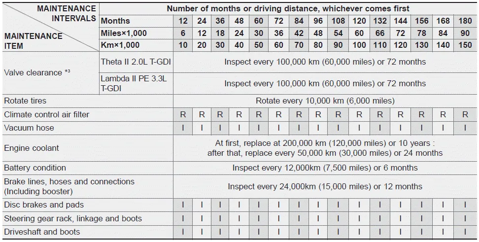
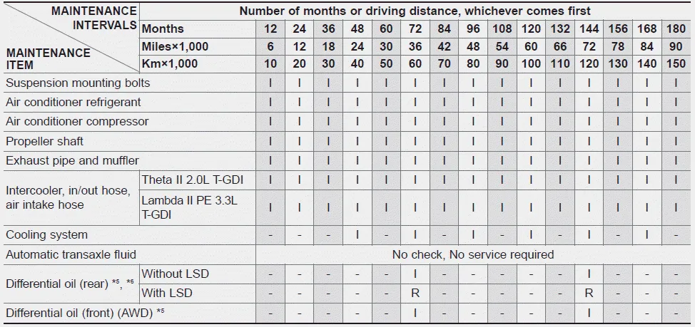
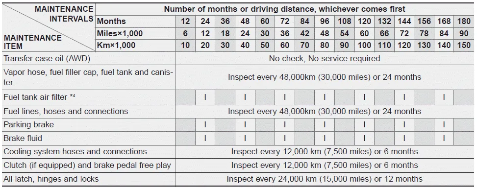
Normal Maintenance Schedule - Turbo Models
The following maintenance services must be performed to ensure good emission control and performance.
Keep receipts for all vehicle emission services to protect your warranty. Where both mileage and time are shown, the frequency of service is determined by whichever occurs first.
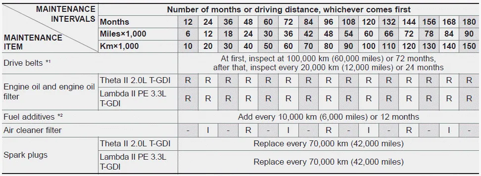
I : Inspect and if necessary, adjust, correct, clean or replace.
R : Replace or change.
*1 : The drive belt should be replaced when cracks occur or tension is reduced.
*2 : If TOP TIER Detergent Gasoline is not available, one bottle of additive is
recommended. Additives are available from your authorized Kia dealer along with
information on how to use them. Do not mix other additives.
Maintenance Under Severe Usage Conditions - Turbo Models
The following items must be serviced more frequently on cars normally used under severe driving conditions. Refer to the chart below for the appropriate maintenance intervals.
R : Replace
I : Inspect and, after inspection, clean, adjust, repair or replace if necessary
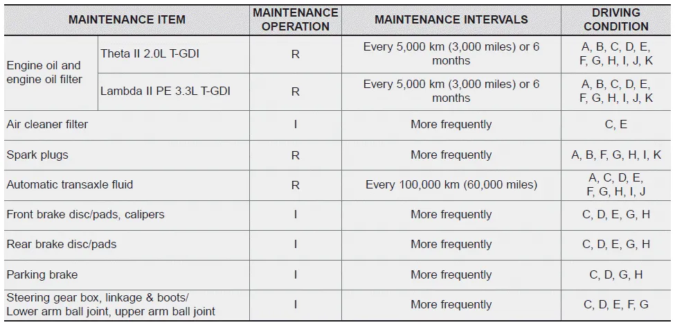
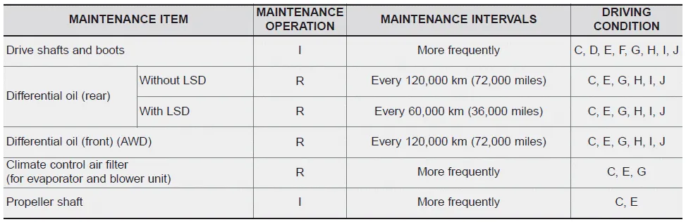
Severe driving conditions
A- Repeatedly driving short distance of less than 8 km (5 miles) in normal temperature
or less than 16 km (10 miles) in freezing temperature
B- Extensive engine idling or low speed driving for long distances
C-Driving on rough, dusty, muddy, unpaved, graveled or saltspread roads
D-Driving in areas using salt or other corrosive materials or in very cold weather
E-Driving in heavy dust condition
F - Driving in heavy traffic area
G- Driving on uphill, downhill, or mountain road repeatedly
H-Towing a Trailer, or using a camper, or roof rack
I -Driving as a patrol car, taxi, other commercial use or vehicle towing
J - Driving over 170 km/h (106 mph)
K-Frequently driving in stop-and-go conditions


Other information:
Kia Stinger (CK) 2018-2023 Owner's Manual: Lift And Support Points
General information Lift And Support Points When heavy rear components such as suspension, fuel tank, spare tire, tailgate and trunk lid are to be removed, place additional weight in the luggage area before hoisting. When substatial weight is removed from the rear of the vehicle, the center of gravity may change and can cause the vehicle to tip forward on the hoist.Kia Stinger (CK) 2018-2023 Owner's Manual: ESP(Electronic Stability Program) System
Components and components location Components Location 1. HECU module 2. Front wheel speed sensor (2WD) 3. Front wheel speed sensor (AWD) 4. Rear wheel speed sensor Description and operation Description of ESP Electronic Stability Program (ESP) recognizes critical driving conditions, such as panic reactions in dangerous situations, and stabilizes the vehicle by wheel-individual braking and engine control intervention.Categories
- Manuals Home
- Kia Stinger Owners Manual
- Kia Stinger Service Manual
- New on site
- Most important about car
Contents
