Kia Stinger CK: What to do in an emergency / Tire Pressure Monitoring System (TPMS)
Kia Stinger (CK) 2018-2023 Owner's Manual / What to do in an emergency / Tire Pressure Monitoring System (TPMS)
Contents:
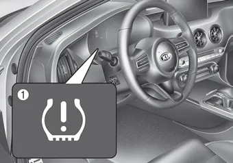
(1) Low tire pressure telltale/ TPMS malfunction indicator
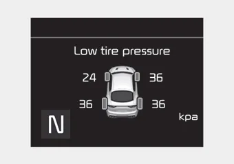
(2) Low tire pressure position telltale (Shown on the LCD display)
Check tire pressure ➤
Low tire pressure telltale ➤
Changing a tire with TPMS ➤


Other information:
Kia Stinger (CK) 2018-2023 Owner's Manual: Driver's Attention
The driver must be cautious in the below situations, because the system may not detect other vehicles or objects in certain circumstances. - The vehicle drives on a curved road or through a tollgate. - The sensor is covered with rain, snow, mud, etc. - The rear bumper, in which the sensor is located, is covered or blocked with a foreign matter such as a sticker, a bumper guard, a bicycle stand, etc.Kia Stinger (CK) 2018-2023 Owner's Manual: Power Tailgate Module
Components and components location Components No. Connector A Connector B Connector C 1 Power supply Cinching motor (+) Spindle motor (RH)_Close (-) 2 Illumination (Tailgate inner switch) Tailgate full open switch Hall sensor (RH)_Power 3 - Tailgate full lock switch SpinCategories
- Manuals Home
- Kia Stinger Owners Manual
- Kia Stinger Service Manual
- New on site
- Most important about car
Contents

Copyright © 2026 www.kstinger.com 0.0075