Kia Stinger CK: Tires and wheels / Tire replacement
Contents:
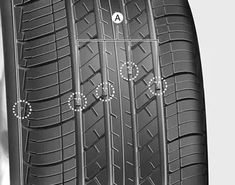
If the tire is worn evenly, a tread wear Indicator (A) will appear as a solid band across the tread. This shows there is less than 1.6 mm (1/16 inch) of tread left on the tire. Replace the tire when this happens.
Do not wait for the band to appear across the entire tread before replacing the tire.
The ABS (Anti-lock Brake System) works by comparing the speed of the wheels. The tire size affects wheel speed. When replacing tires, all 4 tires must use the same size originally supplied with the vehicle. Using tires of a different size can cause the ABS and ESC (Electronic Stability Control) to work irregularly.
✽ NOTICE
We recommend that when replacing tires, use the same which were originally supplied with the vehicle. If not, driving performance could be altered.
Compact spare tire replacement
A compact spare tire has a shorter tread life than a regular size tire. Replace it when you can see the tread wear indicator bars on the tire. The replacement compact spare tire should be the same size and design tire as the one provided with your new vehicle and should be mounted on the same compact spare tire wheel. The compact spare tire is not designed to be mounted on a regular size wheel, and the compact spare tire wheel is not designed for mounting a regular size tire.
Wheel replacement, Tire traction, Tire maintenance
Wheel replacement
When replacing the metal wheels for any reason, make sure the new wheels are equivalent to the original factory units in diameter, rim width and offset.
A wheel that is not the correct size may adversely affect wheel and bearing life, braking and stopping abilities, handling characteristics, ground clearance, body-to-tire clearance, snow chain clearance, speedometer and odometer calibration, headlight aim and bumper height.
CAUTION - Wheel
Wheels that do not meet Kia's specifications may fit poorly and result in damage to the vehicle or unusual handling and poor vehicle control.
Tire traction
Tire traction can be reduced if you drive on worn tires, tires that are improperly inflated or on slippery road surfaces. Tires should be replaced when tread wear indicators appear. Slow down whenever there is rain, snow or ice on the road, to reduce the possibility of losing control of the vehicle.
Tire maintenance
In addition to proper inflation, correct wheel alignment helps to decrease tire wear. If you find a tire is worn unevenly, have your dealer check the wheel alignment.
When you have new tires installed, make sure they are balanced. This will increase vehicle ride comfort and tire life. Additionally, a tire should always be rebalanced if it is removed from the wheel.


Other information:
Kia Stinger (CK) 2018-2023 Owner's Manual: Piston and Connecting Rod
Repair procedures Disassembly In case of removing the high pressure fuel pump, high pressure fuel pipe, delivery pipe, and injector, there may be injury caused by leakage of the high pressure fuel. So don’t do any repair work right after engine stops. • Use fender covers to avoid damaging painted surfaces.Kia Stinger (CK) 2018-2023 Owner's Manual: Vehicle recognition
Some vehicles ahead in your lane cannot be recognized by the sensor as follows: - Narrow vehicles such as motorcycles or bicycles - Vehicles offset to one side - Slow-moving vehicles or suddendecelerating vehicles - Stopped vehicles - Vehicles with small rear profiles such as trailers with no loads A vehicle ahead cannot be recognized correctly by the sensor if any of following occurs: - When the vehicle is pointing upwards due to overloading in the trunk or luggage area.Categories
- Manuals Home
- Kia Stinger Owners Manual
- Kia Stinger Service Manual
- New on site
- Most important about car
Contents
