Kia Stinger CK: Tires and wheels / Tire sidewall labeling
Contents:
- 1. Manufacturer or brand name
- 2. Tire size designation
- 3. Checking tire life (TIN : Tire Identification Number)
- 4. Tire ply composition and material
- 5. Maximum permissible inflation pressure
- 6. Maximum load rating
- 7. Uniform tire quality grading
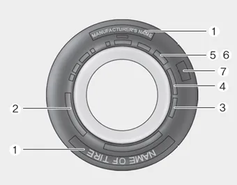
This information identifies and describes the fundamental characteristics of the tire and also provides the tire identification number (TIN) for safety standard certification. The TIN can be used to identify the tire in case of a recall.
1. Manufacturer or brand name
Manufacturer or Brand name is shown.
2. Tire size designation
A tire’s sidewall is marked with a tire size designation. You will need this information when selecting replacement tires for your car. The following explains what the letters and numbers in the tire size designation mean.
Example tire size designation:
(These numbers are provided as an example only; your tire size designator could vary depending on your vehicle.)
P205/55R16 89H
P - Applicable vehicle type (tires marked with the prefix “P’’ are intended for
use on passenger vehicles or light trucks; however, not all tires have this marking).
205 - Tire width in millimeters.
55 - Aspect ratio. The tire’s section height as a percentage of its width.
R - Tire construction code (Radial).
16 - Rim diameter in inches.
89 - Load Index, a numerical code associated with the maximum load the tire can
carry.
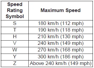
H - Speed Rating Symbol. See the speed rating chart in this section for additional
information.
Wheel size designation
Wheels are also marked with important information that you need if you ever have to replace one. The following explains what the letters and numbers in the wheel size designation mean.
Example wheel size designation: 6.0JX16
6.0 - Rim width in inches.
J - Rim contour designation.
16 - Rim diameter in inches.
Tire speed ratings
The chart below lists many of the different speed ratings currently being used for passenger vehicles. The speed rating is part of the tire size designation on the sidewall of the tire. This symbol corresponds to that tire's designed maximum safe operating speed.
3. Checking tire life (TIN : Tire Identification Number)
Any tires that are over 6 years old, based on the manufacturing date, (including the spare tire) should be replaced by new ones. You can find the manufacturing date on the tire sidewall (possibly on the inside of the wheel), displaying the DOT Code. The DOT Code is a series of numbers on a tire consisting of numbers and English letters. The manufacturing date is designated by the last four digits (characters) of the DOT code.
DOT : XXXX XXXX OOOO
The front part of the DOT means a plant code number, tire size and tread pattern and the last four numbers indicate week and year manufactured.
For example:
DOT XXXX XXXX 1618 represents that the tire was produced in the 16th week of 2018.
WARNING - Tire age
Replace tires within the recommended time frame. Failure to replace tires as recommended can result in sudden tire failure, which could lead to a loss of control and an accident.
4. Tire ply composition and material
The number of layers or plies of rubber- coated fabric in the tire. Tire manufacturers also must indicate the materials in the tire, which include steel, nylon, polyester, and others. The letter "R" means radial ply construction; the letter "D" means diagonal or bias ply construction; and the letter "B" means belted-bias ply construction.
5. Maximum permissible inflation pressure
This number is the greatest amount of air pressure that should be put in the tire. Do not exceed the maximum permissible inflation pressure. Refer to the Tire and Loading Information label for recommended inflation pressure.
6. Maximum load rating
This number indicates the maximum load in kilograms and pounds that can be carried by the tire. When replacing the tires on the vehicle, always use a tire that has the same load rating as the factory installed tire.
7. Uniform tire quality grading ➤


Other information:
Flow diagram Flow Diagram Repair procedures Oil and filter replacement • Prolonged and repeated contact with mineral oil will result in the removal of natural fats from the skin, leading to dryness, irritation and dermatitis.Components and components location Components Schematic diagrams Circuit Diagram [Radio + GPS] [Radio + GPS + DAB] [Radio + GNSS + E-Call] Repair procedures Removal Roof antenna 1. Disconnect the negative (-) battery terminal. 2. Remove the roof trim assembly.Categories
- Manuals Home
- Kia Stinger Owners Manual
- Kia Stinger Service Manual
- 1. Manufacturer or brand name
- 2. Tire size designation
- 3. Checking tire life (TIN : Tire Identification Number)
- 4. Tire ply composition and material
- 5. Maximum permissible inflation pressure
- 6. Maximum load rating
- 7. Uniform tire quality grading
- New on site
- Most important about car
Contents
