Kia Stinger CK: Suspension System / Tire Pressure Monitoring System
Contents:
Components and components location
| Components |
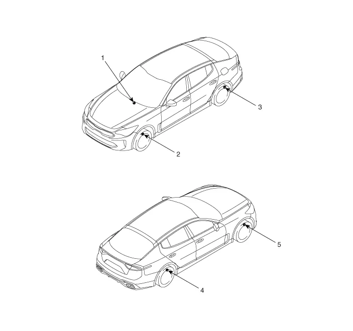
| 1. IBU(TPMS) 2. TPMS sensor (FL) 3. TPMS sensor (RL) |
4. TPMS sensor (RR) 5. TPMS sensor (FR) |
Description and operation
| Description |
TREAD Lamp
| – |
Tire Under Inflation / Leak Warning.
|

| 1. |
Turn on condition
|
| 2. |
Turn off condition
|
DTC Warning
| 1. |
Turn on condition
|
| 2. |
Turn off condition
|
|

System Fault
| 1. |
General Function
|
Troubleshooting
| TPMS Inspection method |
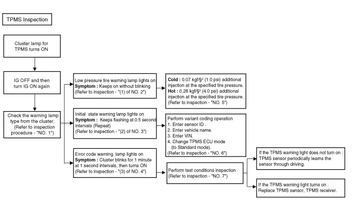
| Inspection |
Find the inspection number by referring to the table above. The following content is irrelevant of the inspection procedure. |
| 1. |
Warning lamp types
|
| 2. |
(1) Check the warning lamp state.
|
| 3. |
(2) Check the warning lamp state.
|

| 4. |
(3) Check the warning lamp state.
|
| 5. |
Low tire pressure warning lamp Cold : Vehicle kept for more than 60 minutes after stopping. → 0.07 kgf/cm² (1.0 psi) additional injection at the specified tire pressure. Hot : Driven vehicle → 0.28 kgf/cm² (4.0 psi) additional injection at the specified tire pressure.
|
| 6. |
Inspect initial state warning lamp
|
| 7. |
DTC checklist for performance test.
|
TPMS Sensor ➤
TPMS Receiver ➤


Other information:
Kia Stinger (CK) 2018-2023 Service Manual: Integrated HomeLink® Wireless Control System
The HomeLink® Wireless Control System provides a convenient way to replace up to three hand-held radiofrequency (RF) transmitters with a single built-in device. This innovative feature will learn the radio frequency codes of most current transmitters to operate devices such as gate operators, garage door openers, entry door locks, security systems, even home lighting.Kia Stinger (CK) 2018-2023 Service Manual: Inside rearview mirror
Adjust the rearview mirror so that the center view through the rear window is seen. Make this adjustment before you start driving. Do not place objects in the rear seat or cargo area which would interfere with your vision through the rear window. WARNING - Mirror adjustment Do not adjust the rearview mirror while the vehicle is moving. This could result in loss of control.Categories
- Manuals Home
- Kia Stinger Owners Manual
- Kia Stinger Service Manual
- New on site
- Most important about car
Contents
