Kia Stinger CK: Tire Pressure Monitoring System / TPMS Receiver
Description and operation
| Operation |
| 1. |
General Function
|
| 2. |
General Conditions to Learn New Sensors:
|
| 3. |
General Conditions to Un-Learn a sensor that is removed :
|
Repair procedures
| Removal |
| 1. |
Turn ignition switch OFF and disconnect the negative (-) battery cable. |
| 2. |
Remove the glove box housing. (Refer to Body - "Glove box housing") |
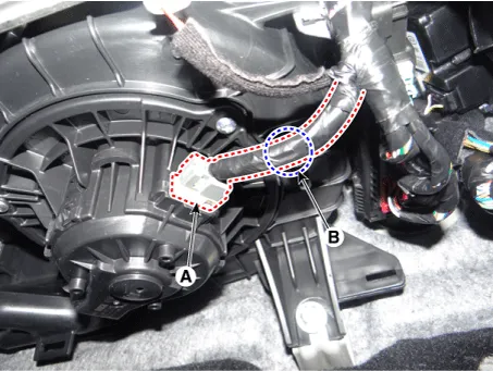
| 3. |
Disconnect the blower motor connector (A) & fix clip (B).
|
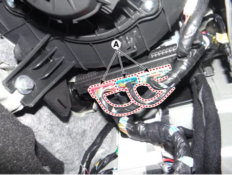
| 4. |
Disconnect the integrated body control unit (IBU) connector (A).
|
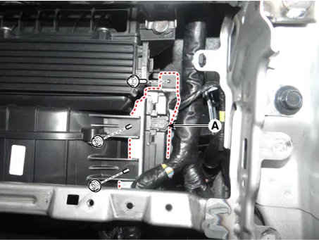
| 5. |
Loosen the nut & bolt and then remove the integrated body control unit (IBU) (A).
|
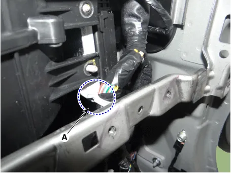
| 6. |
Disconnect the wiring hannes fix clip (A) from the integrated body control unit (IBU).
|
| Diagnosis procedure by using diagnostic device |
The main contents of diagnostic method using diagnostic device are as follows:
| 1. |
Connect self-diagnosis connector (16 pins) located in the lower driver side crash pad to self-diagnosis device, and then turn on the self-diagnosis device after key is ON. |
| 2. |
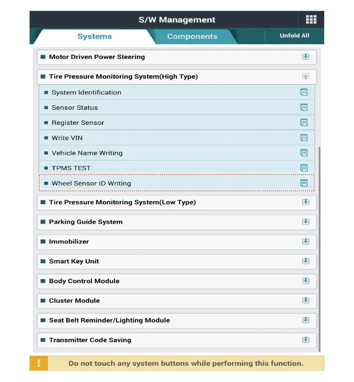
Select the "vehicle model" and "TPMS" on KDS vehicle selection screen, then select OK. |
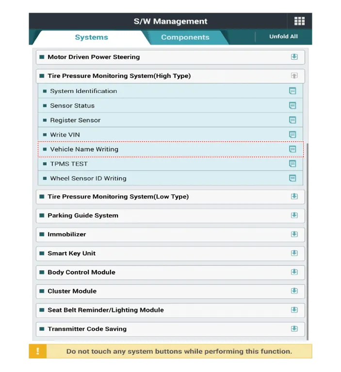
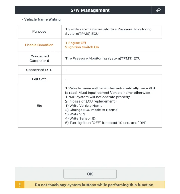
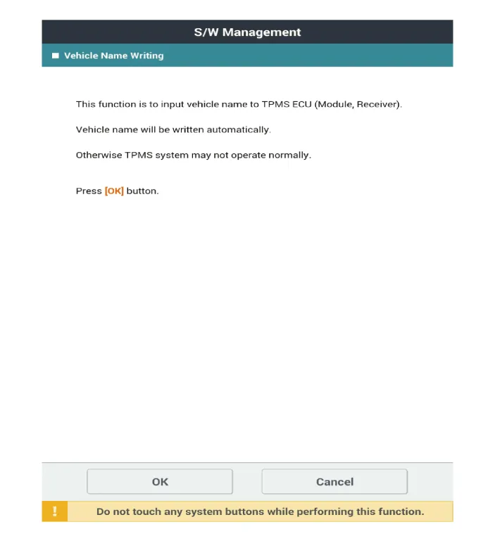
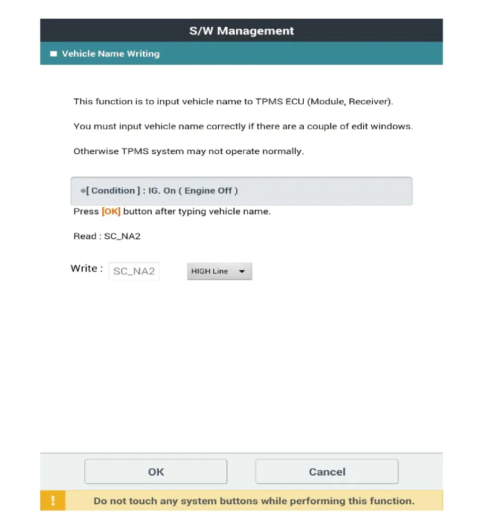
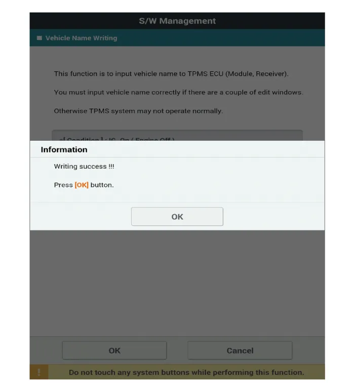
[Vehicle Name Writing Method]
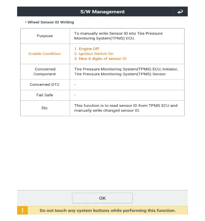
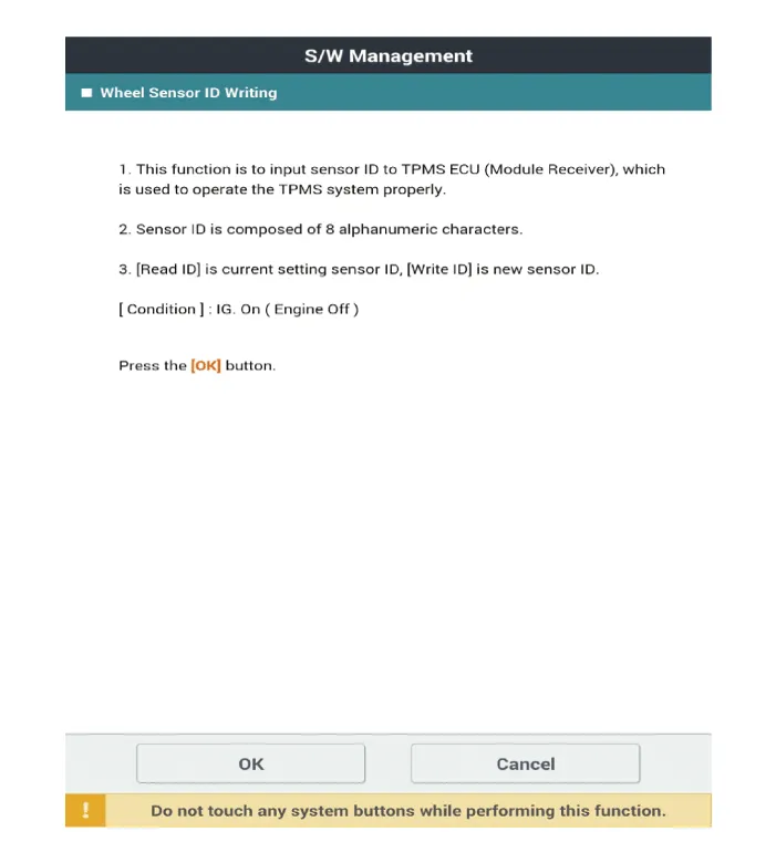
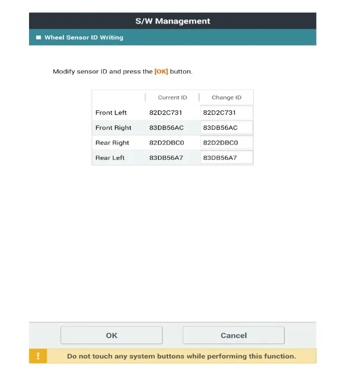
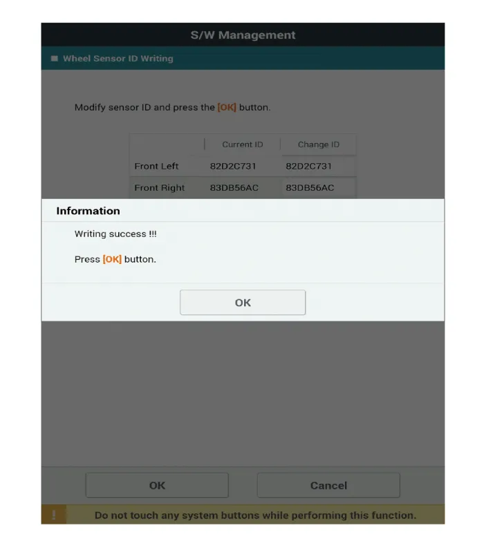
[Wheel Sensor ID Writing Method]


Other information:
Kia Stinger (CK) 2018-2023 Service Manual: Rear Glass Defogger
Components and components location Component Location 1. Integrated body control unit (IBU) 2. Rear glass defogger 3. Rear glass defogger switchComponents and components location Components 1. Console complete 2. Floor console tray 3. Console upper complete 4. Lever boots 5. Console storage box matCategories
- Manuals Home
- Kia Stinger Owners Manual
- Kia Stinger Service Manual
- New on site
- Most important about car
