Kia Stinger CK: Automatic Transmission System / Automatic Transmission System
Components and components location
| Components |
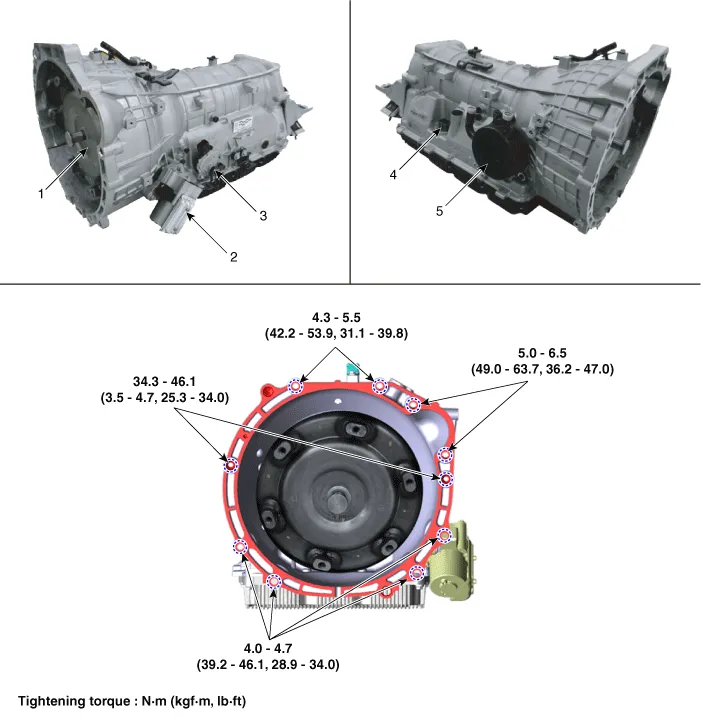
| 1. Torque converter 2. Electric Oil Pump (EOP) 3. Parking switch (Inhibitor switch) |
4. Main connector 5. ATF Warmer |
Repair procedures
| Removal |
| 1. |
Disconnect the negative (-) battery terminal. |
| 2. |
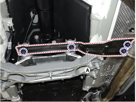
Remove the stay (A) by loosening the bolts.
|
| 3. |
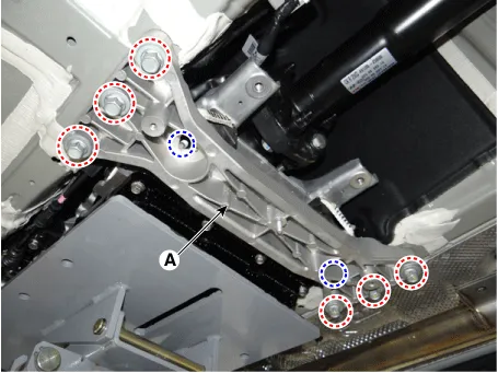
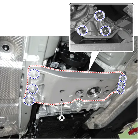
Remove the cross member (A) after supporting the transmission on a jack. [2WD]
[4WD]
|
| 4. |
Remove the front muffler. (Refer to Engine Mechanical System - "Muffler") |
| 5. |
Remove the propeller shaft assembly. (Refer to Driveshaft and axle - "Propeller Shaft Assembly") |
| 6. |
Remove the transfer assembly. (Refer to 4 Wheel Drive (4WD) System- "Transfer Case Assembly") |
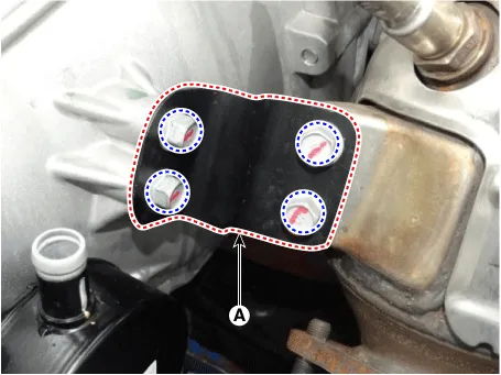
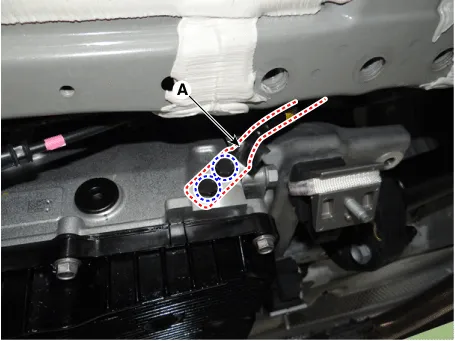
| 7. |
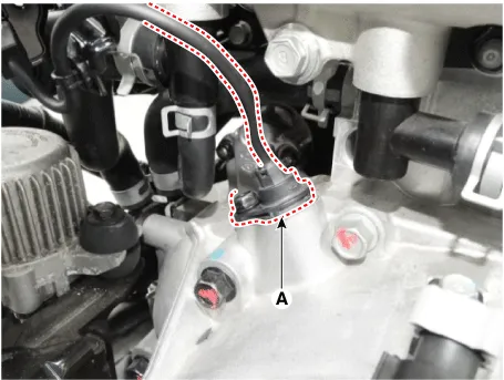
Remove the exhaust manifold stay (A).
|
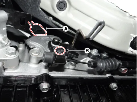
| 8. |
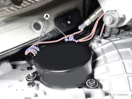
Separate the ATF warmer hose (A). [ATF warmer]
|
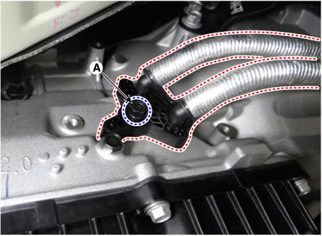
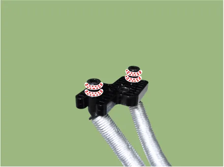
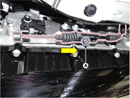
| 9. |
Remove the ATF cooler tube from the transmission after loosening a bolt (A). [Non-ATF warmer]
|

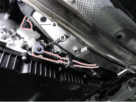
| 10. |
Remove the ground (A).
|
| 11. |
Disconnect the parking switch (inhibitor switch) connector and remove the parking release cable (shift cable). [SBW]
[SBC]
|
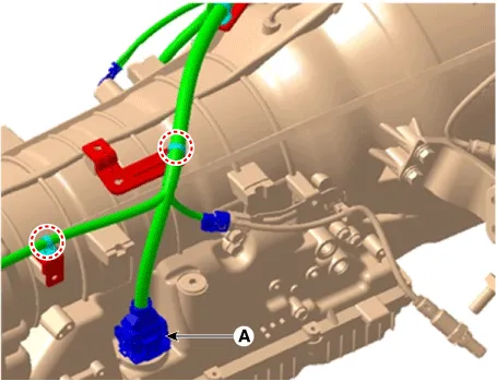
| 12. |
Remove the wiring from the transmission.
|
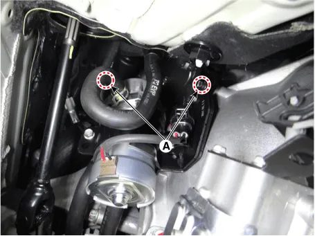
| 13. |
Remove the vacuum pump from the transmission after loosening th bolts (A).
|
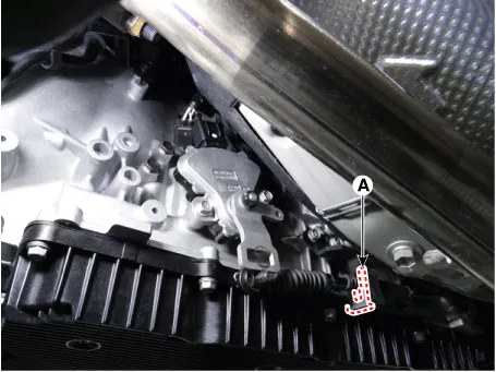
| 14. |
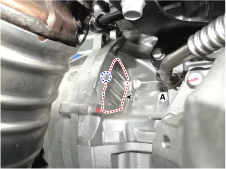
Remove the CKP sensor (A) after loosening a bolt.
|
| 15. |
Remove the cover (A).
|
| 16. |
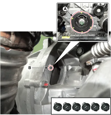
Remove the cover and then loosen the torque converter mounting bolts (B-6pcs) by rotating the crankshaft (A).
|
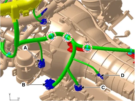
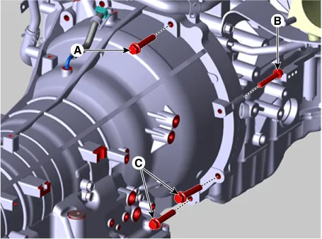
| 17. |
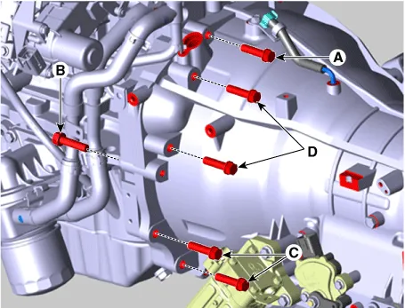
Loosen the transmission mounting bolts (A, B, C) and starter mouting bolts (D).
|

| 18. |
After separating the transmission from the engine, remove the transmission by lowering the jack slowly.
|
| Installation |
| 1. |
Install in the reverse order of removal
|


Other information:
Kia Stinger (CK) 2018-2023 Service Manual: Intake Actuator
Description and operation Description Located in the blower unit, the intake actuator regulates the intake door by a signal from the control unit. Pressing the intake selection switch will shift between recirculation and fresh air modes. Repair procedures Inspection 1. Turn the ignition switch OFF. 2.Kia Stinger (CK) 2018-2023 Service Manual: Adaptive Front-Lighting System (AFS) Unit
Components and components location Components Schematic diagrams Schematic Diagrams Description and operation Description AFS Unit (ECU) AFS located in Cockpit Module is provided information of vehicle (steering wheel signal, vehicle speed, inclination of vehicle). Based on provided information, it calculates algorithm and adjust Low beam of H/Lamp.Categories
- Manuals Home
- Kia Stinger Owners Manual
- Kia Stinger Service Manual
- New on site
- Most important about car
