Kia Stinger CK: Adaptive Front-Lighting System (AFS) / Adaptive Front-Lighting System (AFS) Unit
Components and components location
| Components |
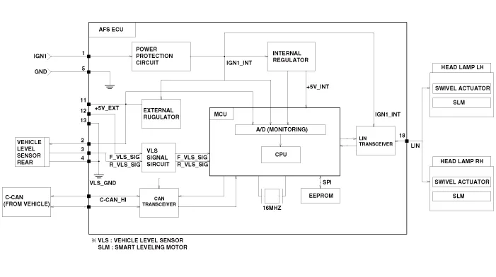
Schematic diagrams
| Schematic Diagrams |
Description and operation
| Description |
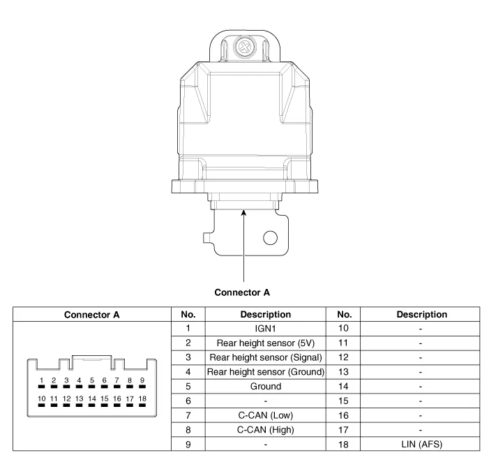
AFS Unit (ECU)
AFS located in Cockpit Module is provided information of vehicle (steering wheel signal, vehicle speed, inclination of vehicle).
Based on provided information, it calculates algorithm and adjust Low beam of H/Lamp.
It transmits driving information by using LIN protocol, it is operated in Fail-safe reaction mode In case system failure occurred.
Repair procedures
| Removal |
|

| 1. |
Disconnect the negative (-) battery terminal. |
| 2. |
Remove the crash pad passenger side panel. (Refer to Body - "Crash Pad Center Panel") |
| 3. |
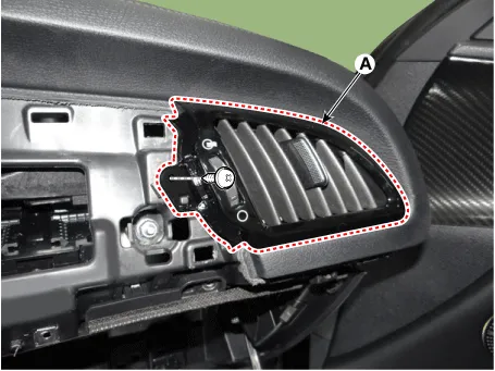
Remove the side airvent duct [RH] (A) after loosening the mounting screw.
|
| 4. |
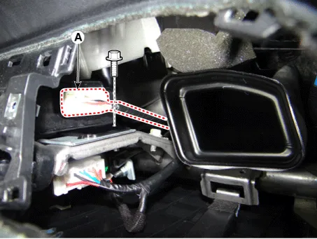
Disconnect AFS unit connector (A) after loosening the mounting bolt.
|
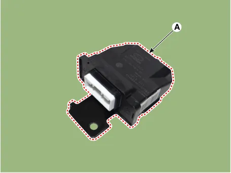
| 5. |
Remove the AFS unit (A).
|
| Installation |
| 1. |
Install the AFS unit. |
| 2. |
Connect the AFS unit connector. |
| 3. |
Install the side airvent duct [RH]. |
| 4. |
Install the crash pad passenger side panel. |
| 5. |
Connect the negative (-) battery terminal.
|


Other information:
Kia Stinger (CK) 2018-2023 Service Manual: Alternator
Specifications Specification ▷ 13.5V, 150A Item Specification Rated voltage 13.5V , 150A Speed in use 0 - 18,000 rpm Pin 1 Voltage regulator IC Regulator built in type Default regulated voltage (V) [COM terminal] 14.Kia Stinger (CK) 2018-2023 Service Manual: Camshaft Position Sensor (CMPS)
Specifications Specifications Item Specification Air Cap (mm) 0.2 - 2.0 Description and operation Description Camshaft Position Sensor (CMPS) is a hall sensor, which detects the camshaft position by using a hall element. It is related with Crankshaft Position Sensor (CKPS) and detects the piston position of each cylinder which cannot be detected by the CKPS.Categories
- Manuals Home
- Kia Stinger Owners Manual
- Kia Stinger Service Manual
- New on site
- Most important about car
