Kia Stinger CK: Automatic Transmission System
Kia Stinger (CK) 2018-2023 Service Manual / Automatic Transmission System
Contents:
Special service tools
| Special Service Tools |
|
Tool Name / Number |
Illustration |
Description |
|
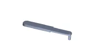
Inhibitor switch guide pin (Parking switch guide pin) 09480-D2100 |
|
Used for fixing "N" range when installing inhibitor switch (Used for fixing "P" range when installing parking switch) |
Troubleshooting
| Troubleshooting |
| Limp Home Mode |
Features a fail-safe function that prevents dangerous situations in the event of a transmission failure. The vehicle will be driven in limp home mode if the transmission malfunctions. In this mode, the transmission operates at a minimal functionality level (fixed shifting, limited shifting, reverse, neutral), making it possible for the vehicle to reach a service center.
Limp Home Mode : Limited shifting Mechanical limp home mode : Fixed shifting (failure of mechanical parts, solenoid valves, TCM, CAN communication) |

|
Trouble symptom |
Suspected area |
Remedy |
|
Shifting delay, Shifting shock, Poor acceleration |
Damaged clutch / brake |
Replace the automatic transmission. |
|
Faulty hydraulic control |
Inspect the solenoid valve. |
|
|
Faulty hydraulic supply |
Inspect the fluid level. |
|
|
Inspect the fluid cleanliness. |
||
|
TCM learning not performed |
Perform the TCM adaptive value learning. |
|
|
Gear lamp (P/R/N/D) of cluster is flashed |
Oil pressure characteristics learning not performed |
Perfrom the oil pressure characteristics learning. |
|
Mechanical limp home mode (locked into 5th) |
Faulty Solenoid valve |
Replace the automatic transmission. |
|
Faulty connector connection |
Inspect the connector connection. |
|
|
Replace the E-module |
||
|
Faulty TCM |
Replace the TCM |
|
|
Limp home mode (locked into 5th, 2nd-5th manual shifting enabled) |
Faulty input speed sensor |
Replace the E-module |
|
Faulty output speed sensor |
Replace the E-module |
|
|
Faulty connector connection |
Inspect the connector connection. |
|
|
Replace the E-module |
||
|
Manual shifting disabled |
Faulty TCM |
Replace the TCM. |
|
Faulty connector connection |
Check the connection of manual mode connector. |
Specifications ➤
Automatic Transmission Control System ➤
Automatic Transmission System ➤
Hydraulic System ➤


Other information:
Kia Stinger (CK) 2018-2023 Service Manual: Specifications
Service data Service Data Items Inner side Outer side Front driveshaft Joint type HUJ#26 WTJ#24 Max. permissible angle 28° 54° Rear driveshaft Joint type CGJ#26 CGJ#26 Max.Kia Stinger (CK) 2018-2023 Service Manual: Driver position memory system
Driver Position Memory System is the facility that enables driver’s seat, leg extension, steering wheel, exterior mirrors, cluster and head-up display (HUD) to be controlled with a simple button operation, which allows a driver to recall memorized driving positions and automatically control them. - Driver’s seat/Leg extension/Steering Wheel/Exterior mirrors: Location - Cluster: Brightness of lighting - Head Up Display (HUD): Height, rotation and brightness.Categories
- Manuals Home
- Kia Stinger Owners Manual
- Kia Stinger Service Manual
- New on site
- Most important about car
Contents

Copyright © 2026 www.kstinger.com 0.0093