Kia Stinger CK: Engine Mechanical System / Cylinder Block
Kia Stinger (CK) 2018-2023 Service Manual / Engine Mechanical System / Cylinder Block
Contents:
Components and components location
| Components |
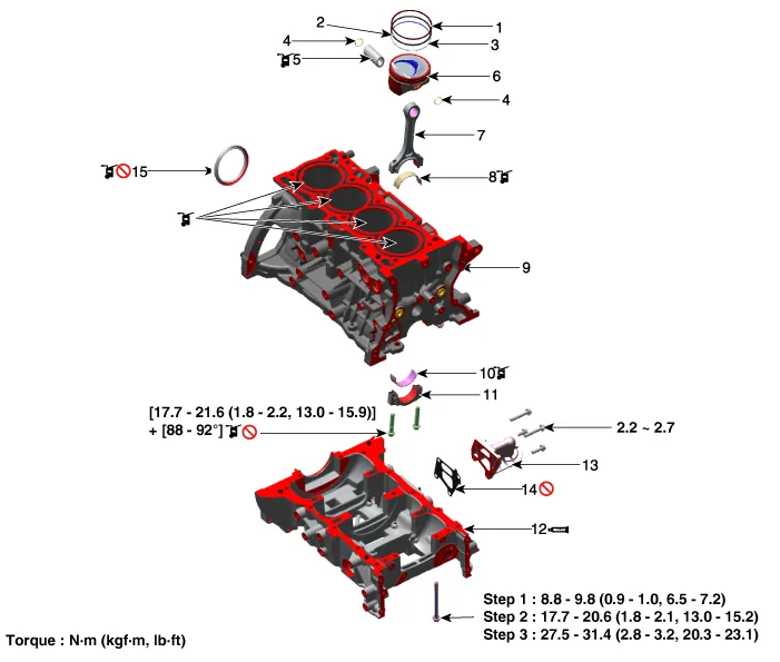
| 1. Piston ring (#1) 2. Piston ring (#2) 3. Oil ring 4. Snap ring 5. Piston pin 6. Piston 7. Connecting rod |
8. Connecting rod upper bearing
9. Cylinder block 10. Connecting rod lower bearing 11. Connecting rod bearing cap 12. Ladder frame 13. Oil filter bracket 14. Oil filter bracket gasket 15. Rear oil seal |
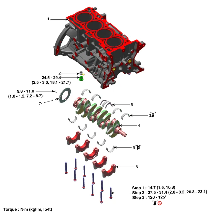
| 1. Cylinder block 2. Piston cooling oil jet 3. Crankshaft upper bearing 4. Crankshaft |
5. Crankshaft lower bearing
6. Thrust bearing 7. Crankshaft position sensor (CKPS) wheel 8. Main bearing cap |
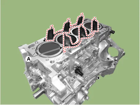
Water Jacket Separator
Repair procedures
| Removal and Installation |
| 1. |
Remove the cylinder head. (Refer to Cylinder Head Assembly - "Cylinder Head") |
| 2. |
Remove the water jacket separator (A).
|
| 3. |
Install the other parts in the reverse order of removal. |
Drive Plate ➤
Rear Oil Seal ➤
Piston and Connecting Rod ➤
Crankshaft ➤
Cylinder Block ➤


Other information:
Kia Stinger (CK) 2018-2023 Service Manual: Integrated Memory Seat (IMS) Unit
Components and components location Components Connector Pin Information No Connector A Connector B Connector C 1 Cushion extension motor (Front) Battery (+) Slide switch (Front) 2 Recline motor (Front) Ground Recline switch (Front) 3 Rear height motor (Up) Battery (+) FKia Stinger (CK) 2018-2023 Service Manual: Automatic transmission operation
The automatic transmission has 8 forward speeds and one reverse speed. The individual speeds are selected automatically in the D (Drive) position. WARNING To reduce the risk of serious injury or death: ALWAYS check the surrounding areas near your vehicle for people, especially children, before shifting a vehicle into D (Drive) or R (Reverse).Categories
- Manuals Home
- Kia Stinger Owners Manual
- Kia Stinger Service Manual
- New on site
- Most important about car
Contents

Copyright © 2026 www.kstinger.com 0.0111