Symptoms
|
Possible Causes
|
Remedy
|
Coolant leakage
|
| • |
From the bleed hole of the water pump
|
|
Visually check
|
| • |
Check leaks after about ten-minute warming up.
|
|
| • |
If coolant still leaks, replace a water pump.
|
|
| • |
If leakage stops, reuse the water pump (Do not replace the pump
with a new one).
|
|
|
|
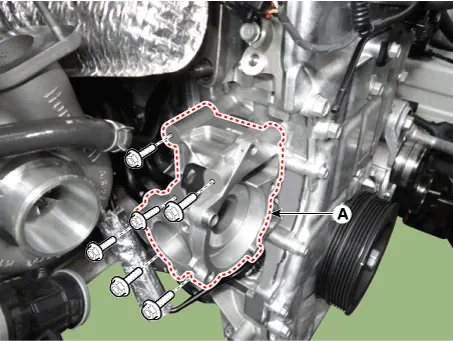
| • |
Check the tightening of the water pump mounting bolts.
|
|
| • |
Retighten the mounting bolts.
|
|
| • |
Check damage of gaskets or inflow of dust.
|
|
| • |
Replace the gasket and clean dust off.
|
|
| • |
From outer surface of water pump
|
|
| • |
Check the material or any cracks of the water pump.
|
|
| • |
Poor material. If any crack found, replace the water pump.
|
|
Noise
|
|
Inspection with a stethoscope
|
| • |
After starting the engine, check noise with a stethoscope.
|
|
| • |
If there is no noise, reuse the water pump(do not replace it).
|
|
| • |
If there is any noise from the water pump, remove the drive belt
and recheck.
|
|
Inspection after removing a drive belt
|
| • |
After removing a water pump and a drive belt, check noise again.
|
|
| • |
If there is noise, reuse the water pump. Check other drive line
parts.
|
|
| • |
If there is no noise, replace the water pump with a new one.
|
|
Inspection after removing a water pump
|
| • |
After removing a water pump and a drive belt, check noise again.
|
|
| • |
If there is any interference between them, replace the water
pump with a new one.
|
|
Overheating
|
|
Loosened impeller
|
| • |
Corrosion of the impeller wing
|
|
| • |
Poor coolant quality / Maintenance check
|
|
| • |
Impeller seperation from the shaft
|
|
| • |
Replace the water pump.
|
|
Other information:
Kia Stinger (CK) 2018-2023 Service Manual: Crash Pad
Components and components location
Components
1. Cowl cross member bar
2. Main wiring
3. Main crash pad
4. Side air vent duct [RH]
5. Crash pad under cover [RH]
6. Crash pad lower panel [RH]
7. Crash pad center lower cover
8. Glove box housing
9. Fuse A/S cover
10. Crash pad garnish [RH]
11.
Kia Stinger (CK) 2018-2023 Service Manual: Rear Cross Member
Repair procedures
Removal
1.
Remove wheel nuts, wheel and tire (A) from hub.
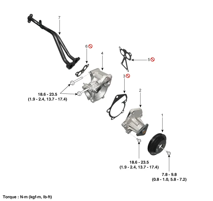
Tightening torque:
107.9 - 127.5 N·m (11.0 - 13.0 kgf·m, 79.6 - 94.0 lb·ft)
Be careful not to damage the wheel bolts when removing the wheel
and tire (A).