Kia Stinger CK: Engine Mechanical System / Cooling System
Kia Stinger (CK) 2018-2023 Service Manual / Engine Mechanical System / Cooling System
Contents:
- Coolant
- Cooling Fan
- Radiator
- Reservoir Tank
- Water Temperature Control Assembly
- Electric Thermostat (ECT)
- Water pump
Components and components location
| Components |
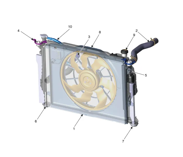
| 1. Radiator 2. Radiator upper hose 3. Radiator lower hose 4. Radiator upper mounting bracket (RH) 5. Radiator upper mounting bracket (LH) |
6. Radiator lower mounting insulator
(RH) 7. Radiator lower mounting insulator (LH) 8. Cooling fan assembly 9. Reservoir tank 10. Reservoir hose |
Troubleshooting
| Engine Overheat Troubleshooting |
|
Inspection |
Remedy |
||||||||
|
Visual inspection |
Inspect for shortage of coolant in reservoir tank . |
Reinspect after replenishing coolant. |
|||||||
Inspect for coolant pollution after removing radiator cap.
|
Reinspect after replacing coolant. |
||||||||
|
Inspect for leakage and loose coolant hoses (radiator hose, heater hose,
oil cooler hose, etc.). |
Reinspect for leakage after reinstalling hoses and clamps. |
||||||||
|
Inspect for leakage on water inlet fitting mounting part. |
Reinspect for leakage after replacing O-ring. |
||||||||
|
Reinspect for leakage after tightening to the specified torque. |
|||||||||
|
Inspect drive belt (for normal operation of water pump). |
Adjust drive belt tension or replace. |
||||||||
|
Inspect for leakage on water pump gasket mounting part. |
Reinspect for leakage after replacing gasket. |
||||||||
|
Reinspect for leakage after tightening to the specified torque. |
|||||||||
|
Inspect for loose coolant temperature sensor, cooling fan connector and
pin. |
Reinstall loose connector. |
||||||||
|
Replace relevant part if connector pin is damaged. |
|||||||||
|
Inspect operation status of cooling fan. - Check operation status by switching ON/OFF the heater control A/C.
|
Check mounting status of ground cable. |
||||||||
|
Diagnostic device |
Inspect self-diagnostic code using KDS/GDS. |
Check coolant temperature sensor, wiring, connector, etc. |
|||||||
|
Unit inspection |
Inspect water pump impeller. |
Replace water pump. |
|||||||
|
Inspect for foreign materials and status of thermostat valve. |
Inspect unit after removing foreign materials. |
||||||||
|
Inspect for stuck thermostat valve. - Immerse thermostat in water heated to over 95°C (203°F), then heat for at least 3 minutes to check valve lift.
|
Check valve lift. - Replace thermostat if valve lift is below specification or valve is stuck. |
||||||||


Coolant ➤
Cooling Fan ➤
Radiator ➤
Reservoir Tank
Repair procedures
| Removal |
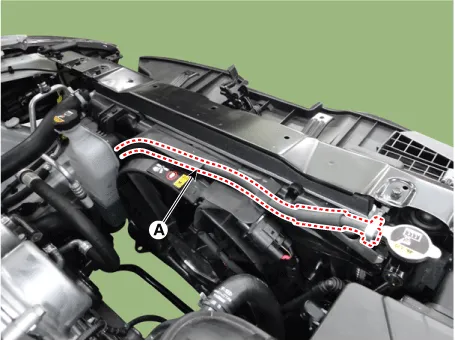
| 1. |
Disconnect the reservoir hose (A).
|
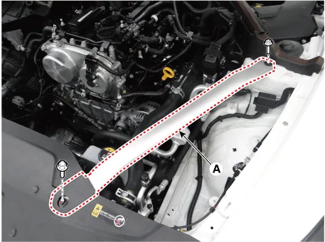
| 2. |
Remove the LH front strut bar (A).
|
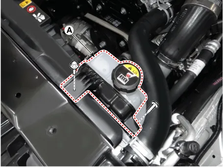
| 3. |
Remove the reservoir tank (A).
|
| 4. |
Install in the reverse order of removal. |
Water Temperature Control Assembly ➤
Electric Thermostat (ECT) ➤
Water pump ➤


Other information:
Kia Stinger (CK) 2018-2023 Service Manual: P Position Solenoid Valve (ON/OFF)
Specifications Specifications Item Specification Control type ON/OFF Control pressure kpa (kgf/cm², psi) 539.36 (5.5, 78.23) Current (mA) 0 - 600 Coil resistance (Ω) 10.5 ± 0.5 Components and components location Components Location 1.Components and components location Component Location 1. Front console armrest Repair procedures Replacement Put on gloves to protect your hands. • Use a plastic panel removal tool to remove interior trim pieces without marring the surface.Categories
- Manuals Home
- Kia Stinger Owners Manual
- Kia Stinger Service Manual
- Coolant
- Cooling Fan
- Radiator
- Reservoir Tank
- Water Temperature Control Assembly
- Electric Thermostat (ECT)
- Water pump
- New on site
- Most important about car
Contents

Copyright © 2026 www.kstinger.com 0.009