
Kia Stinger CK: Fuses And Relays / Relay Box (Passenger Compartment)
Components and components location
| Component Location |
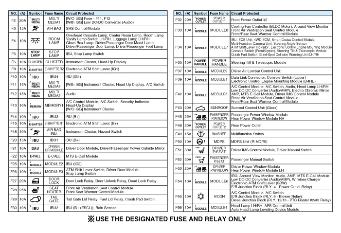
| Integrated central control unit (ICU) |

| Circuit (ICU Junction Block) |
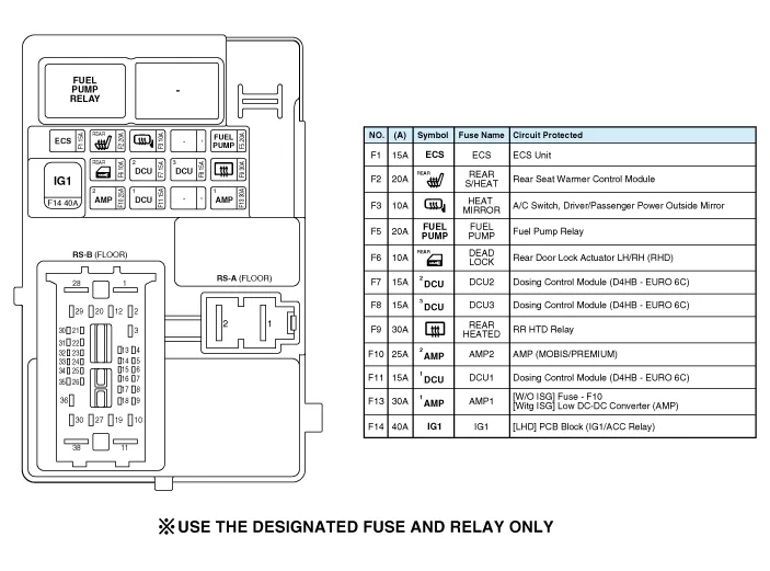
| Rear Sub Junction Block |
Description and operation
| Description |
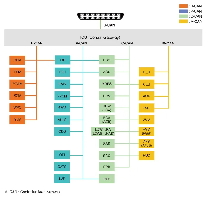
Communication Network Diagram
|
Abbreviation |
Explanation |
|
ACU |
Airbag Control Unit |
|
AFL |
Adaptive Front-Lighting System |
|
AMP |
Amplifier |
|
AUDIO |
Audio Head Unit |
|
AVM |
Around View Monitor |
|
B_CAN |
Body Controller Area Network |
|
BCW |
Blind-Spot Collision Warning |
|
C_CAN |
Chassis Controller Area Network |
|
CDP |
Compact Disk Player |
|
CLU |
Cluster Module |
|
DATC |
Dual Automatic Temp Control |
|
DDM |
Driver Door Module |
|
ECM |
Engine Control Module |
|
F_PUMP |
Fuel Pump Control Module |
|
HUD |
Head Up Display |
|
IBU |
Integrated Body Control Unit |
|
ICU |
Integrated Central Control Unit |
|
IFB |
Interface Box |
|
IMS |
Integrated Memory System |
|
LDW |
Lane Departure Warning |
|
LKA |
Land Keeping Assist |
|
M_CAN |
Multi media Controller Area Network |
|
MDPS |
Motor Driven Power Steering |
|
MFC |
Multi Function Camera |
|
MTC |
Manual Temp Control |
|
ODS |
Occupant Detection System |
|
P_CAN |
Powertrain Controller Area Network |
|
PCM |
Powertrain control module |
|
PTG |
Power Tailgate Module |
|
RVM |
Rear View Monitor |
|
SCC |
Smart Cruise Control |
|
SCM |
Steering Column Module |
|
TCM |
Transmission Control Module |
|
VDC |
Vehicle Dynamic Control |
|
WPC |
Wireless Power Charger |
Integrated Central Control Unit (ICU)
ICU (Integrated Central Control Unit) is an integrated model of smart junction block and central gateway.
It performs the function of conventional "Smart junction block" and the function of communication medium of "Central Gateway".

Central Gateway (CGW)
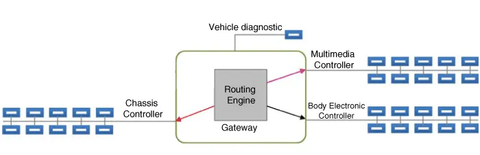
CGW is a controller enabling communication among the controllers connected to the different networks.
There are five CAN networks connected to CGW. B-CAN and M-CAN are connected to the low-speed CAN, C-CAN and P-CAN to the high-speed CAN while D-CAN is connected for inspection.
| 1. |
CGW Main Features
|


| 2. |
How to check CGW
|

Smart Junction Block(SJB)
Smart Junction Block (SJB) is a module that performs the function of conventional Junction Box and some functions of BCM.
It controls various components including lamps by using CAN communication and IPS (replacing the function of fuse and relay) or ARISU.
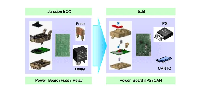
IPS stands for Intelligent Power Switch, which uses the semiconductor technology to replace the current role of fuse and relay.
The IPS chip has two functions :
1) the high current-based component control;
2) component protection from overcurrent.
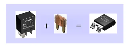
The advantages of IPS are as follows:
|
SJB control entry
| 1. |
Switch signal input
|
| 2. |
SJB protection
|
| 3. |
SJB fail safe function
|
| 4. |
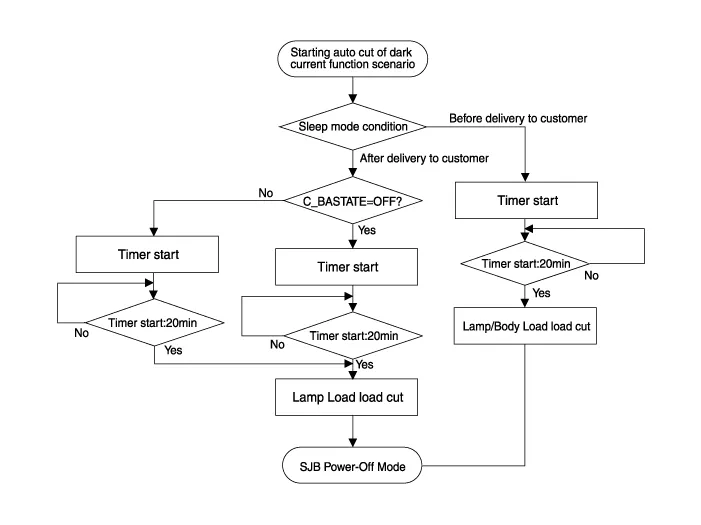
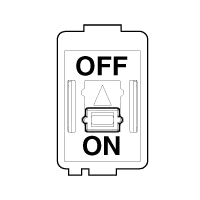
Auto Cut System of Dark Current
|



Repair procedures
| Fuse Inspection |
| 1. |
Check that the fuse holders are loosely held and that the fuses are securely fixed by the holders. |
| 2. |
Check that each fuse circuit has the exact fuse capacity. |
| 3. |
Check the fuses for any damage.
|
| Diagnosis with KDS |
| 1. |
In the body electrical system, failure can be quickly diagnosed by using the vehicle diagnostic system (KDS). The diagnostic system (KDS) provides the following information.
|
| 2. |
Select the 'Car model' and the 'Integrated Body Control Unit (IBU)' to be checked in order to check the vehicle with the tester. |
| 3. |
Select the 'Current Data' menu to search the current state of the input/output data. |
| 4. |
To forcibly actuate the input value of the module to be checked, select option 'Actuation Test' |
| 5. |
If you want to change user option, select "user option". |
| Removal |
Integrated Central Control Unit (ICU)
| 1. |
Disconnect the negative (-) battery terminal. |
| 2. |
Remove the crash pad lower panel. (Refer to Body - "Crash Pad Lower Panel") |
| 3. |
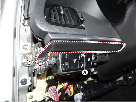
Remove the crash pad garnish [LH] (A) after loosening the mounting screw.
|
| 4. |
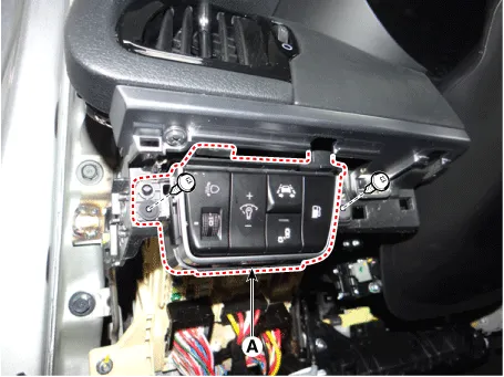
Remove the side crash pad switch (A) after loosening the mounting screws.
|
| 5. |
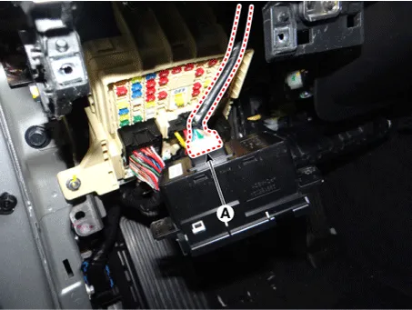
Disconnect the side crash pad switch connector (A).
|
| 6. |
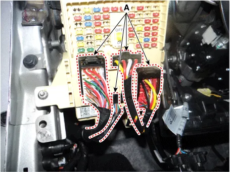
Disconnect the connectors (A) from the fuse side of the integrated central control unit (ICU).
|
| 7. |
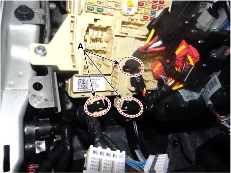
Remove the mounting clips (A) from the integrated central control unit (ICU).
|
| 8. |
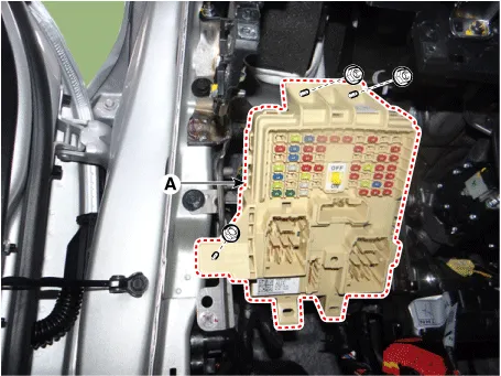
Remove the integrated central control unit (ICU) (A) after loosening the mounting nuts.
|
| 9. |
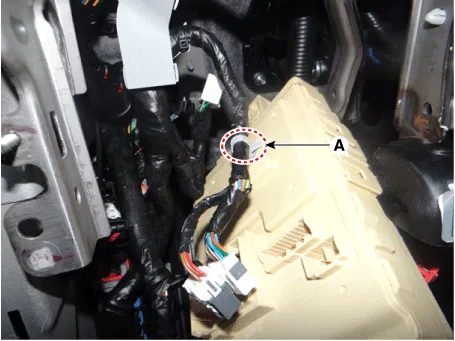
Disconnect the connectors (A) from the back of the integrated central control unit (ICU).
|

| 10. |
Remove the mounting clip (A) from the integrated central control unit (ICU).
|
Rear Sub Junction Block (RSJB)
| 1. |
Disconnect the negative (-) battery terminal. |
| 2. |
Remove the luggage side trim [RH]. (Refer to Body - "Luggage Side Trim") |
| 3. |
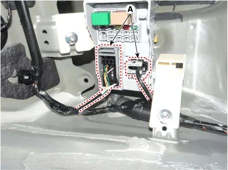
Disconnect the rear sub junction block (RSJB) connectors (A)
|
| 4. |
Remove the rear sub junction block (RSJB) (A) after loosening the mounting nuts.
|

| Installation |
Integrated Central Control Unit (ICU)
| 1. |
Install the mounting clip from the integrated central control unit (ICU). |
| 2. |
Connect the integrated central control unit (ICU) connectors. |
| 3. |
Install the integrated central control unit (ICU). |
| 4. |
Install the mounting clip from the integrated central control unit (ICU). |
| 5. |
Connect the integrated central control unit (ICU) connectors. |
| 6. |
Connect the side crash pad switch connector. |
| 7. |
Install the side crash pad switch. |
| 8. |
Install the crash pad garnish [LH]. |
| 9. |
Install the crash pad lower panel. |
| 10. |
Connect the negative (-) battery terminal. |
Rear Sub Junction Block (RSJB)
| 1. |
Install the rear sub junction block (RSJB). |
| 2. |
Connect the rear sub junction block (RSJB) connectors. |
| 3. |
Install the luggage side trim [RH]. |
| 4. |
Connect the negative (-) battery terminal. |


Other information:
Kia Stinger (CK) 2018-2023 Service Manual: Engine Mounting
Components and components location Components 1. Engine mounting support bracket (LH) 2. Engine mounting support bracket (RH) 3. Engine mounting bracket (LH) 4. Engine mounting bracket (RH) 5. Transmission mounting bracket (AWD) 6. Transmission mounting bracket (2WD) Repair procedures Removal and Installation Engine Mounting Bracket 1.Kia Stinger (CK) 2018-2023 Service Manual: Manifold Absolute Pressure Sensor (MAPS)
Specifications Specification Item Specification Output Voltage (V) 5 Pressure (KPa) 32.5 - 284 Operating Voltage (V) 4.5 - 5.5 Pressure [kPa (kgf/cm², psi)] Output Voltage (Vref = 5V) 32.Categories
- Manuals Home
- Kia Stinger Owners Manual
- Kia Stinger Service Manual
- New on site
- Most important about car
