Kia Stinger CK: Engine Control System / Barometric Pressure Sensor (BPS)
Specifications
Item
|
Specification
|
Output Voltage (V)
|
5
|
Pressure (KPa)
|
32.5 - 284
|
Operating Voltage (V)
|
4.5 - 5.5
|
Pressure
[kPa (kgf/cm², psi)]
|
Output Voltage (Vref = 5V)
|
32.5 (0.33, 4.71)
|
0.5
|
70 (0.71, 10.1)
|
1.1
|
270 (2.75, 39.1)
|
4.3
|
284 (2.89, 41.1)
|
4.5
|
Description and operation
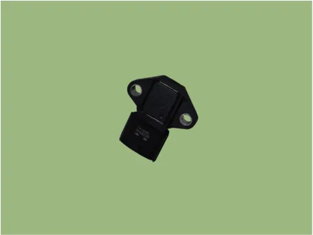
Installed on the intercooler assembly, the Boost Pressure Sensor (BPS) measures
the pressure of compressed air in the turbocharger.
The BPS consists of a piezo-electric element and a hybrid IC amplifying the element's
output signal. The element is silicon diaphragm type and adapts pressure sensitive
variable resistor effect of semi-conductor. One side of silicon diaphragm is 100%
vacuum and turbocharger pressure is applied on the other side. Hence, output is
gained from the silicon variation in proportion to the pressure change.
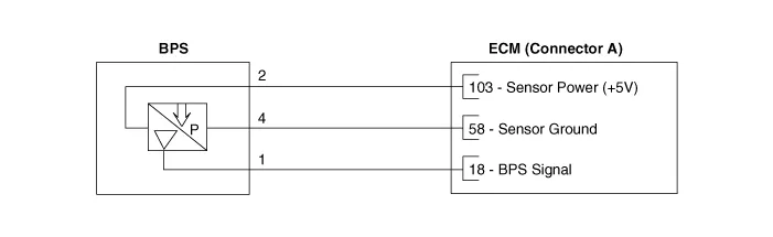
Schematic diagrams
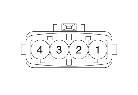
Harness Connector
Repair procedures
| 1. |
Connect the KDS on the Data Link Connector (DLC).
|
| 2. |
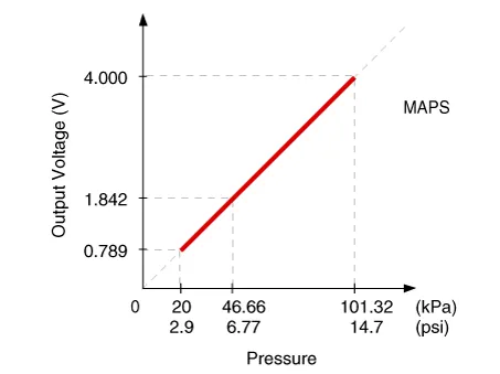
Measure the output voltage of the BPS during idle with IG ON.
Pressure
[kPa (kgf/cm², psi)]
|
Output Voltage (V) [Vref=5V]
|
20.0 (0.20, 2.9)
|
0.79
|
46.7 (0.47, 6.77)
|
1.84
|
101.3 (1.03, 14.7)
|
4.0
|
|
| 1. |
Switch "OFF" the ignition and disconnect the negative (-) battery terminal.
|
| 2. |
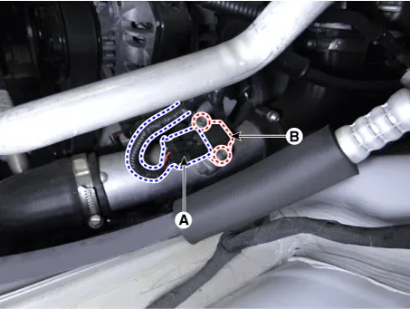
Disconnect the boost pressure sensor connector (A).
|
| 3. |
Remove the mounting bolts (B), and then remove the sensor from the intercooler
outlet pipe.
|
Boost pressure sensor mounting bolt :
9.8 - 11.8 N·m (1.0 - 1.2 kgf·m, 7.2 - 8.7 lb·ft)
|
|
| • |
Install the component to the specified torques.
|
| • |
Note that internal damage may occur when the component is dropped.
If the component has been dropped, inspect before installing.
|
| • |
Insert the sensor in the installation hole and be careful not
to damage it.
|
|
| 1. |
Install in the reverse order of removal.
|
Other information:
Kia Stinger (CK) 2018-2023 Service Manual: How to use the Smart Liftgate
The liftgate can be opened with notouch activation satisfying all the conditions
below.
After 15 seconds when all doors are closed and locked
Positioned in the detecting area for more than 3 seconds.
✽ NOTICE
• The Smart Liftgate does not operate when:
- The smart key is detected within 15 seconds after the doors are closed and
locked, and is continuously detected.
Kia Stinger (CK) 2018-2023 Service Manual: Parking Switch
Specifications
Specifications
Specifications
Item
Specification
Output type
PWM (S1, S2), ON/OFF (Ps, Ns)
Power supply (V)
5 (S1, S2), 12 (Ps, Ns)
Signal code table
Signal
P
Not P
S1
5 V
0
S2
0
5 V
Ps
12 V
0
Ns
0
12 V
Components and components location
Components Location
1.


