Kia Stinger CK: Fuses And Relays / Relay Box (Engine Compartment)
Components and components location
| Component Location |
| E/R Junction Block (LHD - 1/2) |
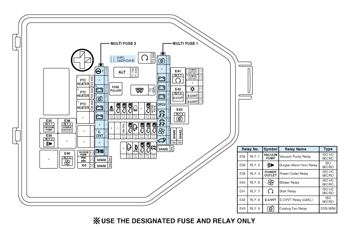
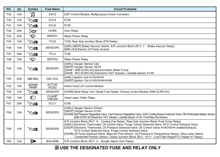
| Circuit (E/R Junction Block (LHD - 2/2) |

| E/R Junction Block (RHD - 1/2) |
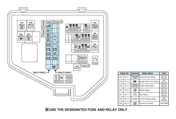
| Circuit (E/R Junction Block (RHD - 2/2)) |
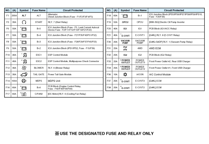
| PCB Block |
| Circuit (PCB Block) |
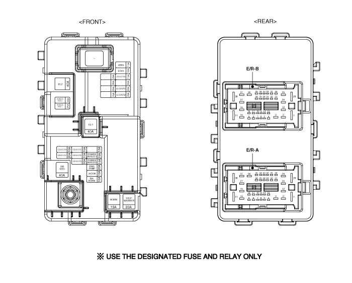
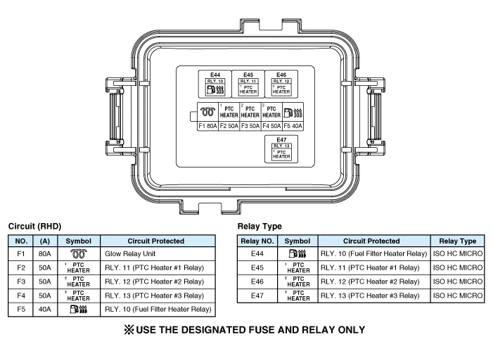
| Diesel Junction Block (D4HB : R 2.2L TCI) |
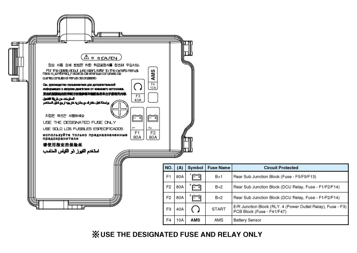
| Battery Junction Block |
Repair procedures
| Inspection |
| 1. |
Disconnect the negative (-) battery terminal. |
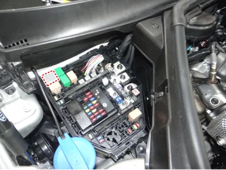
| 2. |
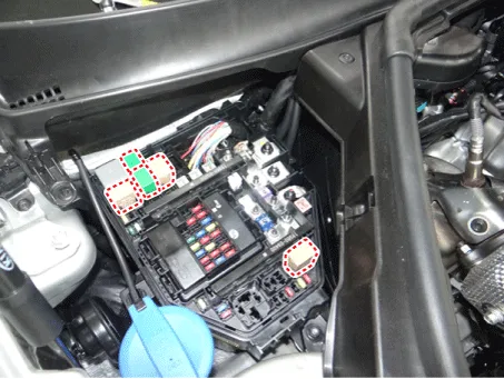
Pull out the relay from the engine compartment relay block. |
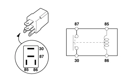
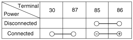
Power Relay (Type A)
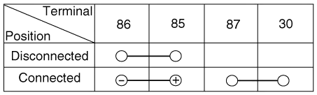
Check for continuity between the terminals.
| 1. |
After supplying power to between No. 85 and 86 power relay terminals, check that there is continuity between No. 30 and 87 terminals. |
| 2. |
After disconnecting power between No. 85 and 86 power relay terminals, check that there is no continuity between No. 30 and 87 terminals. Engine Room Relay Block
|
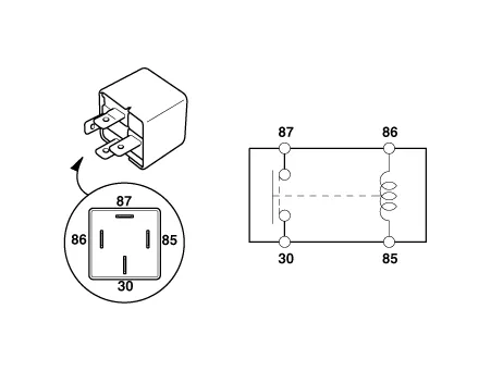
Power Relay (Type B)
Check for continuity between the terminals.
| 1. |
After supplying power to between No. 85 and 86 power relay terminals, check that there is continuity between No. 30 and 87 terminals. |
| 2. |
After disconnecting power between No. 85 and 86 power relay terminals, check that there is no continuity between No. 30 and 87 terminals.
|
Metal Core PCB Block
| 1. |
Disconnect the negative (-) battery terminal. |
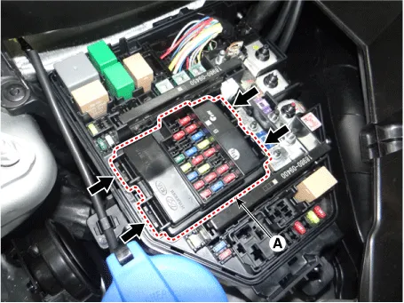
| 2. |
Push the four hooks in the direction of the arrow and lift up the metal core PCB block (A). |
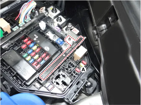
| 3. |
Remove the metal core PCB block by disconnecting the connectors.
|
Fuse
| 1. |
Check that the fuse holders are loosely held and that the fuses are securely fixed by the holders. |
| 2. |
Check that each fuse circuit has the exact fuse capacity. |
| 3. |
Check the fuses for any damage.
|

Multi Fuse
| 1. |
Disconnect the negative (-) battery terminal. |
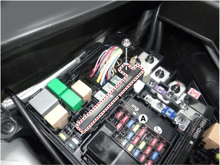
| 2. |
Remove the multi fuse (A) after loosening the mounting nut.
|
| 3. |
Install in the reverse order of removal.
|


Other information:
Kia Stinger (CK) 2018-2023 Service Manual: A/C Pressure Transducer
Description and operation Description A/C pressure transducer measures the pressure in high pressure line and converts it into voltage. Based on the converted voltage, engine ECU controls cooling fan by operating it at high or low speed. Engine ECU stops the operation of compressor when the temperature of refrigerant line is too high or low irregularly to optimize air conditioning system.Kia Stinger (CK) 2018-2023 Service Manual: P Position Solenoid Valve (ON/OFF)
Specifications Specifications Item Specification Control type ON/OFF Control pressure kpa (kgf/cm², psi) 539.36 (5.5, 78.23) Current (mA) 0 - 600 Coil resistance (Ω) 10.5 ± 0.5 Components and components location Components Location 1.Categories
- Manuals Home
- Kia Stinger Owners Manual
- Kia Stinger Service Manual
- New on site
- Most important about car
