Kia Stinger CK: Cylinder Block / Cylinder Block
Repair procedures
| Disassembly |
In case of removing the high pressure fuel pump, high pressure fuel pipe, delivery pipe, and injector, there may be injury caused by leakage of the high pressure fuel. So don’t do any repair work right after engine stops. |

|

Mark all wiring and hoses to avoid misconnection |

| 1. |
Remove the engine and transmission assembly. (Refer to Engine and Transmission Assembly - "Engine and Transmission Assembly") |
| 2. |
Remove the automatic transmission. (Refer to Automatic Transmission System - "Automatic Transmission") |
| 3. |
Remove the drive plate. (Refer to Cylinder Block - "Drive Plate") |
| 4. |
Remove the front driveshaft. (If equipped with AWD system) (Refer to Driveshaft and Axle - "Front Driveshaft") |
| 5. |
Remove the front differential assembly. (If equipped with AWD system) (Refer to Driveshaft and Axle - "Front Differential Carrier") |
| 6. |
Remove the rear oil seal. (Refer to Cylinder Block - "Rear Oil Seal") |
| 7. |
Install the engine assembly to engine stand for disassembly. |
| 8. |
Remove the intake manifold. (Refer to Intake and Exhaust System - "Intake Manifold") |
| 9. |
Remove the exhaust manifold. (Refer to Intake and Exhaust System - "Turbocharger & Exhaust Manifold") |
| 10. |
Remove the timing chain. (Refer to Timing System - “Timing Chain”) |
| 11. |
Remove the cylinder head assembly. (Refer to Cylinder Head Assembly - "Cylinder Head") |
| 12. |
Remove the A/C compressor. (Refer to Heating, Ventilation Air conditioning - "Compressor") |
| 13. |
Remove the alternator. (Refer to Engine Electrical System - "Alternator") |
| 14. |
Remove the cylinder head assembly. (Refer to Cylinder Head Assembly - "Cylinder Head") |
| 15. |
Remove the water temperature control assembly. (Refer to Cooling System - "Water Temperature Control Assembly") |
| 16. |
Remove the balance shaft & oil pump. (Refer to Lubrication System - "Balance Shaft & Oil Pump") |
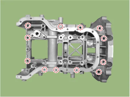
| 17. |
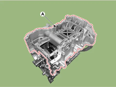
Remove the ladder frame.
|
| 18. |
Remove the piston & connecting rod assembly. (Refer to Cylinder Block - "Piston and Connecting Rod") |
| 19. |
Remove the crankshaft. (Refer to Cylinder Block - "Crankshaft") |
| 20. |
Remove the knock sensor. (Refer to Engine Control/Fuel System - "Knock Sensor") |
| 21. |
Remove the crankshaft Position Sensor (CKPS). (Refer to Engine Control/Fuel System - "Crankshaft Position Sensor") |
| 22. |
Remove the oil pressure Switch. (Refer to Lubrication System - "Oil Pressure Switch") |
| 23. |
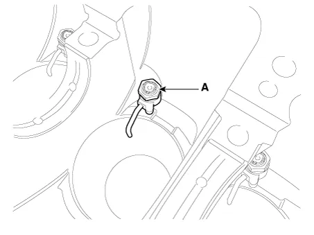
Remove the oil jet (A).
|
| Inspection |
| 1. |
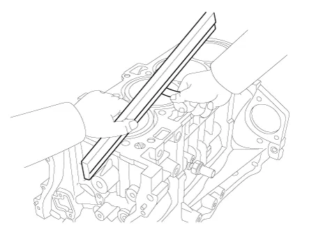
Remove gasket material. Using a gasket scraper, remove all the gasket material from the top surface of the cylinder block. |
| 2. |
Clean cylinder block Using a soft brush and solvent, thoroughly clean the cylinder block. |
| 3. |
Inspect top surface of cylinder block for flatness. Using a precision straight edge and feeler gauge, measure the contacting surface of the cylinder block and the manifolds for warpage.
|
| 4. |
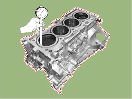
Inspect cylinder bore diameter. Visually check the cylinder for vertical scratchs. If deep scratches are present, replace the cylinder block. |
| 5. |
Inspect cylinder bore diameter. Using a cylinder bore gauge, measure the cylinder bore diameter at position in the thrust and axial directions.
|
| Reassembly |
| 1. |
Install the oil jet (A).
|
| 2. |
Install the oil pressure switch. (Refer to Lubrication System - "Oil Pressure Switch") |
| 3. |
Install the crankshaft position sensor (CKPS). (Refer to Engine Control/Fuel System - "Crankshaft Position Sensor") |
| 4. |
Install the knock sensor. (Refer to Engine Control/Fuel System - "Knock Sensor") |
| 5. |
Install the crankshaft. (Refer to Cylinder Block - "Crankshaft") |
| 6. |
Install the piston & connecting rod assembly. (Refer to Cylinder Block - "Piston and Connecting Rod") |
| 7. |
Apply liquid gasket to the mating surface of cylinder block and ladder frame.
|
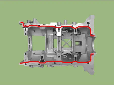
| 8. |
Install ladder frame (A).
|
| 9. |
Install the other parts in reverse order of removal.
|


Other information:
Kia Stinger (CK) 2018-2023 Service Manual: Cylinder Head Cover
Repair procedures Removal • Use fender covers to avoid damaging painted surfaces. • To avoid damage, unplug the wiring connectors carefully while holding the connector portion. Mark all wiring and hoses to avoid misconnection.Kia Stinger (CK) 2018-2023 Service Manual: Securing a child restraint with a lap/shoulder belt
When not using the LATCH system, all child restraints must be secured to a vehicle rear seat with the lap part of a lap/shoulder belt. Automatic locking mode Since all passenger seat belts move freely under normal conditions and only lock under extreme or emergency conditions (emergency locking mode), you must manually pull the seat belt all the way out to shift the retractor to the “Automatic Locking” mode to secure a child restraint.Categories
- Manuals Home
- Kia Stinger Owners Manual
- Kia Stinger Service Manual
- New on site
- Most important about car
