
Kia Stinger CK: Cylinder Head Assembly / Cylinder Head Cover
Repair procedures
| Removal |
|

Mark all wiring and hoses to avoid misconnection. |

| 1. |
Disconnect the battery negative terminal. |
| 2. |
Remove the engine cover. (Refer to Engine and Transmission Assembly - "Engine Cover") |
| 3. |
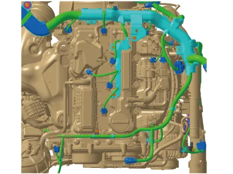
Disconnect the wiring connectors and harness clamps and remove the connector brackets around the cylinder head cover.
|
| 4. |
Remove the ignition coils. (Refer to Engine Electrical System - “Ignition Coil”) |
| 5. |
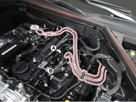
Disconnect the fuel hose (A) and PCSV (Purge control solenoid valve) hose (B).
|
| 6. |
Remove the high pressure fuel pump. (Refer to Engine Control/Fuel System - "High Pressure Fuel Pump") |
| 7. |
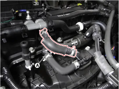
Disconnect the positive crankcase ventilation (PCV) hose (A).
|
| 8. |
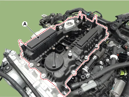
Remove the cylinder head cover (A).
|
| Installation |
| 1. |
Install cylinder head cover.
|
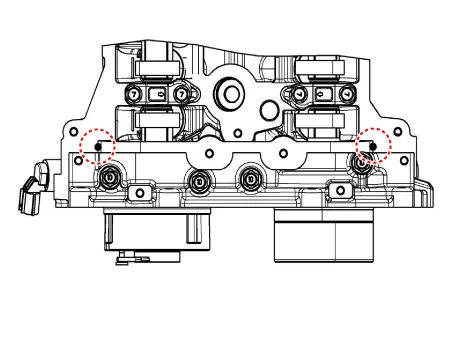

| 2. |
Install the other parts in the reverse order of removal. |


Other information:
Kia Stinger (CK) 2018-2023 Service Manual: Integrated Memory Seat (IMS) Switch
Components and components location Components Repair procedures Removal 1. Disconnect the negative (-) battery terminal. 2. Remove the driver front door trim. (Refer to Body - "Front Door Trim") 3. Disconnect the intergrated memory seat switch connector (A).Kia Stinger (CK) 2018-2023 Service Manual: 7. Uniform tire quality grading
Quality grades can be found where applicable on the tire sidewall between tread shoulder and maximum section width. For example: TREADWEAR 440 TRACTION A TEMPERATURE A Tread wear The tread wear grade is a comparative rating based on the wear rate of the tire when tested under controlled conditions on a specified government test course. For example, a tire graded 150 would wear one-and-ahalf times (1½) as well on the government course as a tire graded 100.Categories
- Manuals Home
- Kia Stinger Owners Manual
- Kia Stinger Service Manual
- New on site
- Most important about car
