Kia Stinger CK: Electric Power Steering / Steering Column and Shaft
Repair procedures
| Replacement |
[LHD]
| 1. |
Disconnect the battery negative cable. |
| 2. |
Turn the steering wheel so that the front wheels are facing straight ahead. |
| 3. |
Remove the driver airbag. (Refer to Restraint - "Driver Airbag (DAB) Module and Clock Spring") |
| 4. |
Disconnect the steering wheel connector.
|

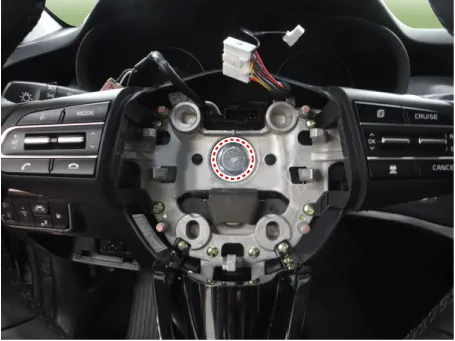
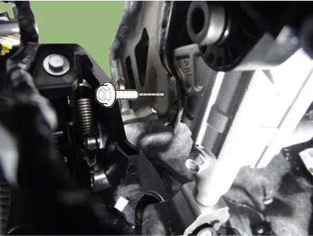
| 5. |
Loosen the steering wheel bolt and then remove the steering wheel.
|

| 6. |
Remove the crash pad lower panel. (Refer to Body -"Crash pad lower panel") |
| 7. |
Remove the steering column shroud lower panel. (Refer to Body -"Steering Column Shroud Panel") |
| 8. |
Remove the clock spring. (Refer to Restraint - "Driver Airbag (DAB) Module and Clock Spring") |
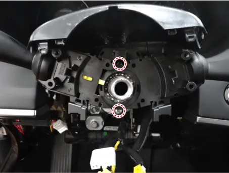
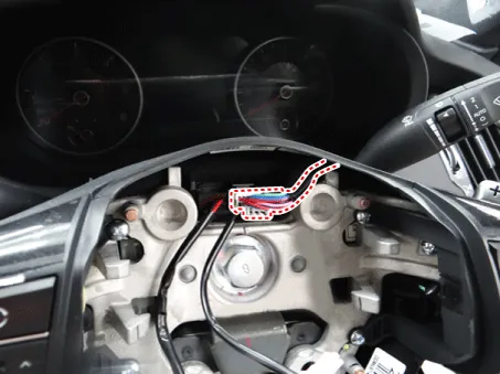
| 9. |
Loosen the multi function switch screw and then disconnect the multi function connector.
|

| 10. |
Remove the knee airbag. (Refer to Restraint - "Knee airbag (KAB)") |
| 11. |
Remove the under cover. D 2.2 R VGT (Refer to Engine Mechanical System - "Engine Room Under cover") G 2.0 T-GDI THETA II (Refer to Engine Mechanical System - "Engine Room Under cover") G 3.3 T-GDI LAMBDA II (Refer to Engine Mechanical System - "Engine Room Under cover") |
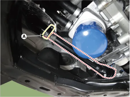
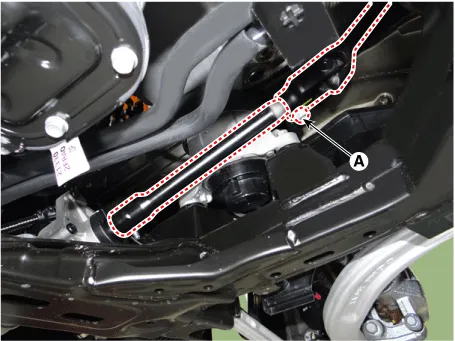
| 12. |
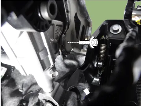
Loosen the bolt (A) and then separate the universal joint from the shaft joint.
|
| 13. |
Disconnect the SCM actuator connector.
|


| 14. |
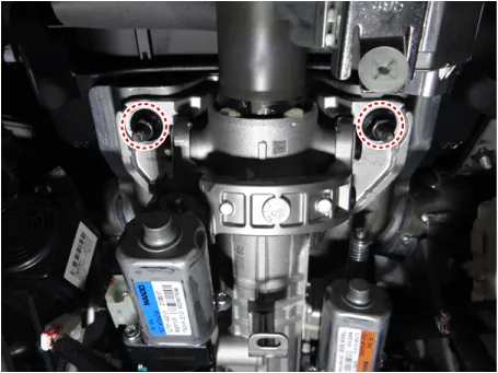
Loosen the steering column nuts.
|
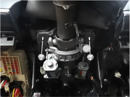
| 15. |
Loosen the steering column bolt.
|
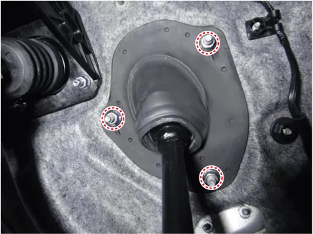
| 16. |
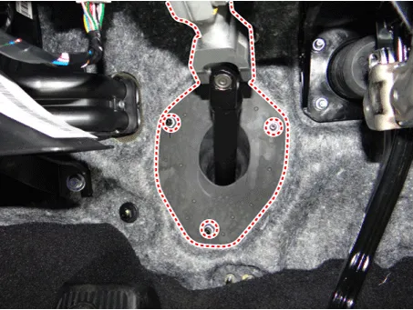
Loosen the steering column dust cover nuts and then remove the steering column.
|
| 17. |
Install in the reverse order of removal. |
[RHD]
| 1. |
Disconnect the battery negative cable. |
| 2. |
Turn the steering wheel so that the front wheels are facing straight ahead. |
| 3. |
Remove the driver airbag. (Refer to Restraint - "Driver Airbag (DAB) Module and Clock Spring") |
| 4. |
Disconnect the steering wheel connector.
|
| 5. |
Loosen the steering wheel bolt and then remove the steering wheel.
|

| 6. |
Remove the crash pad lower panel. (Refer to Body -"Crash pad lower panel") |
| 7. |
Remove the steering column shroud lower panel. (Refer to Body -"Steering Column Shroud Panel") |
| 8. |
Remove the clock spring. (Refer to Restraint - "Driver Airbag (DAB) Module and Clock Spring") |
| 9. |
Loosen the multi function switch screw and then disconnect the multi function connector.
|
| 10. |
Remove the knee airbag. (Refer to Restraint - "Knee airbag (KAB)") |
| 11. |
Remove the under cover. D 2.2 R VGT (Refer to Engine Mechanical System - "Engine Room Under cover") G 2.0 T-GDI THETA II (Refer to Engine Mechanical System - "Engine Room Under cover") G 3.3 T-GDI LAMBDA II (Refer to Engine Mechanical System - "Engine Room Under cover") |
| 12. |
Loosen the bolt (A) and then separate the universal joint from the shaft joint.
|
| 13. |
Disconnect the SCM actuator connector.
|
| 14. |
Loosen the steering column nuts.
|
| 15. |
Loosen the steering column bolt.
|
| 16. |
Loosen the steering column dust cover nuts and then remove the steering column.
|
| 17. |
Install in the reverse order of removal. |
| Inspection |
| 1. |
Check the steering column for damage and deformation. |
| 2. |
Check the joint bearing for damage and wear. |
| 3. |
Check the tilt bracket for damage and cracks. |


Other information:
Kia Stinger (CK) 2018-2023 Service Manual: Master Cylinder
Components and components location Components 1. Master cylinder 2. Brake booster 3. Brake reservoir Repair procedures Removal [LHD] 1. Turn ignition switch OFF and disconnect the negative (-) battery cable. 2. Remove the brake fluid from the master cylinder reservoir with a syringe.Kia Stinger (CK) 2018-2023 Service Manual: Electric Power Steering
Description and operation Description EPS (Electric power steering, Column assist type) system is an engine operation independent steering system that uses an electric motor to assist the steering force. EPS control module controls the motor operation based on input signals from torque sensor and steering angle sensor via CAN (Controller Area Network), resulting in a more precise and timely control of steering assist thatn conventional engine-driven hydraulic systems.Categories
- Manuals Home
- Kia Stinger Owners Manual
- Kia Stinger Service Manual
- New on site
- Most important about car
