Kia Stinger CK: Electric Power Steering / Steering Gear box
Components and components location
| Components |
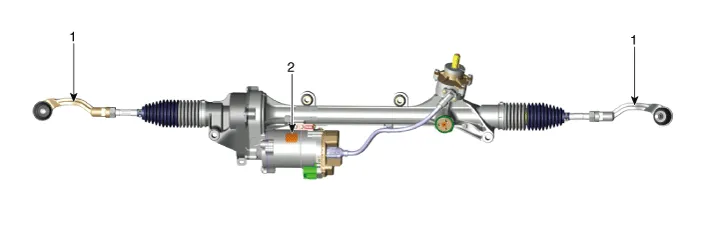
| 1. Tie rod end |
2. R-MDPS motor |
Repair procedures
| Removal |
| 1. |
Remove wheel nuts, front wheel and tire (A) from hub.
|


| 2. |
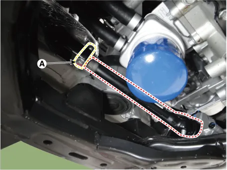
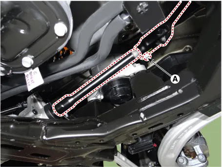
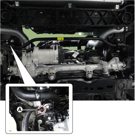
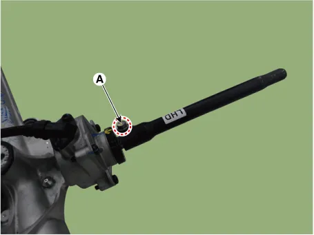
Loosen the bolt (A) and then separate the universal joint from the shaft joint.
[LHD]
[RHD]
|
| 3. |
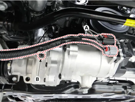
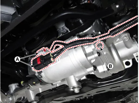
Disconnect the R-MDPS connector (A) and clip (B). [LHD]
[RHD]
|
| 4. |
Disconnect the R-MDPS wiring clip (A) from the sub frame.
|
| 5. |
Remove the tie rod end nut.
|
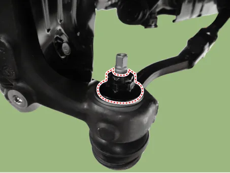
| 6. |
Remove the knuckle by using the ball joint remover (A).
|
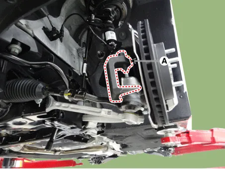
| 7. |
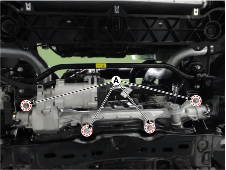
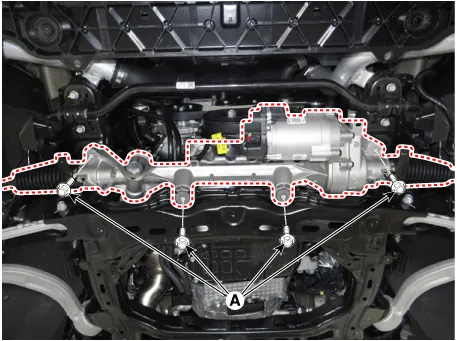
Loosen the gear box bolts (A) and then remove the gear box. [LHD]
[RHD]
|
| 8. |
Loosen the shaft joint bolt (A) from the gear box.
|
| 9. |
Check the front alignment. (Refer to Suspension System - "Alignment") |
| 10. |
Install in the reverse order of removal. |
| 11. |
Register "ASP calibration EPS type recognition" by GDS after replacing steering column assembly. (Refer to Electric Power Steering - "Repair procedures") |


Other information:
Kia Stinger (CK) 2018-2023 Service Manual: Field Effect Transistor (DATC)
Repair procedures Inspection 1. Turn the ignition switch ON. 2. Manually operate the control switch and measure the voltage of the blower motor. 3. Operate the control switch to raise the voltage up to high speed. Specification Fan Speed Manual Control Auto Control 1 4.Kia Stinger (CK) 2018-2023 Service Manual: Auto Lighting Control System
Specifications Specifications Items Specifications Rated voltage 5V Load Max. 1mA (Relay load) Illuminations (LUX) 50 0.98 ± 0.2 V 150 1.74 ± 0.38 V Components and components location Component Location 1.Categories
- Manuals Home
- Kia Stinger Owners Manual
- Kia Stinger Service Manual
- New on site
- Most important about car
