Kia Stinger CK: AVN System / AVN Antenna
Components and components location
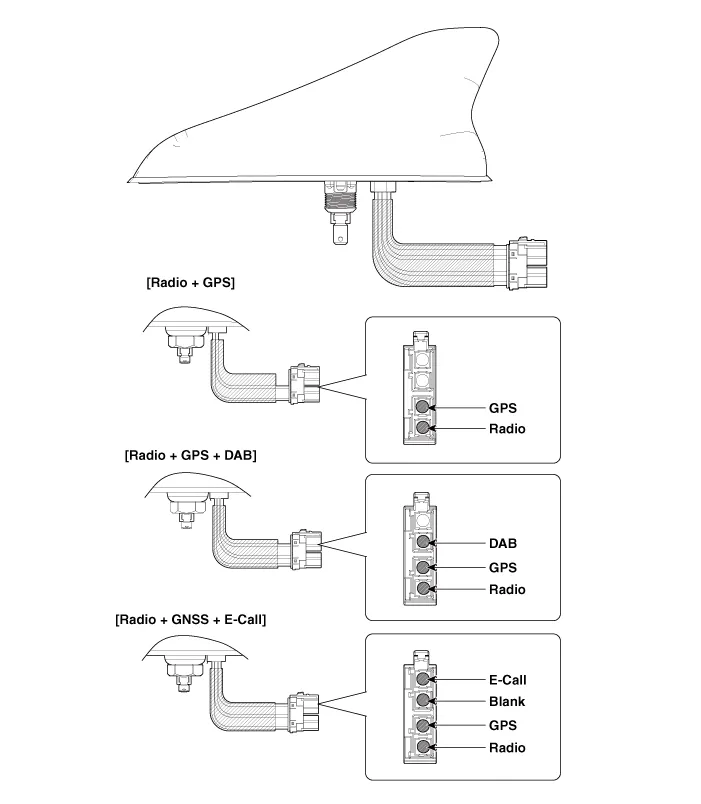
| Components |
Schematic diagrams
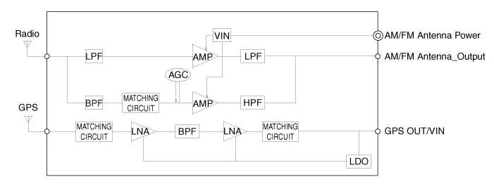
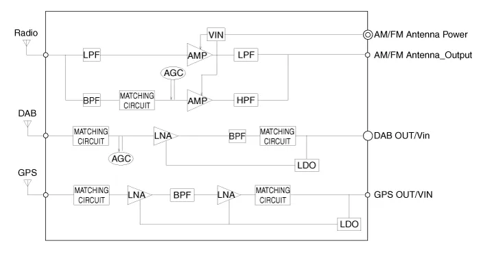
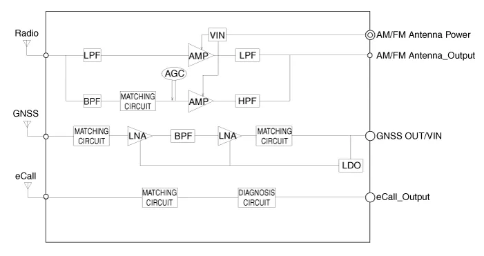
| Circuit Diagram |
[Radio + GPS]
[Radio + GPS + DAB]
[Radio + GNSS + eCall]
Repair procedures
| Removal |
AVN antenna
| 1. |
Disconnect the negative (-) battery terminal. |
| 2. |
Remove the roof trim assembly. (Refer to Body - "Roof Trim Assembly") |
| 3. |
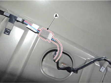
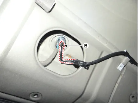
Disconnect the roof antenna main connector (A) and roof antenna power connector (B).
|
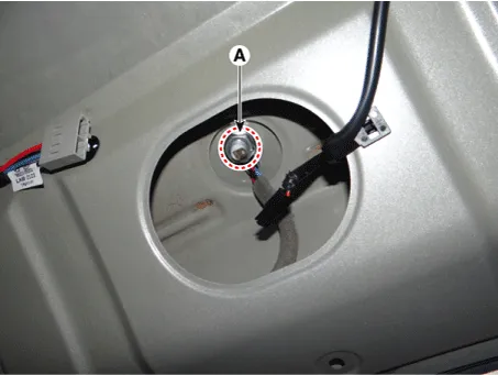
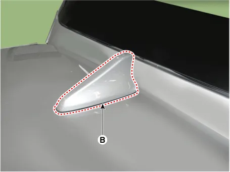
| 4. |
Remove the roof antenna (B) after loosening a nut (A).
|
| Installation |
AVN antenna
| 1. |
Install the roof antenna. |
| 2. |
Connect the roof antenna main connector and roof antenna power connecter. |
| 3. |
Install the roof trim assembly. |
| 4. |
Connect the negative (-) battery terminal.
|

| Inspection |
Antenna Cable
| 1. |
Check for continuity between the center poles of antenna cable.
|
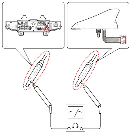
| 2. |
Check for continuity between the outer poles of antenna cable. There should be continuity.
|
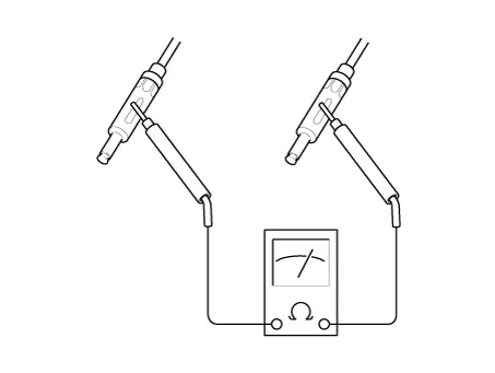
| 3. |
If there is no continuity, replace the antenna cable. |
| 4. |
Check for continuity between the center pole (A) and outer pole (B) of antenna cable. There should be no continuity.
|
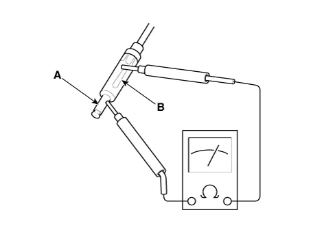
| 5. |
If there is continuity, replace the antenna cable. |


Other information:
Kia Stinger (CK) 2018-2023 Service Manual: Roof Trim
Components and components location Components (1) [General Type] 1. Roof trim 2. Sunvisor 3. Assist handle bracket Components (2) [Panorama Sunroof Type] 1. Roof trim 2. Sunvisor 3. Assist handle bracketKia Stinger (CK) 2018-2023 Service Manual: Explanation of scheduled maintenance items
Engine oil and filter The engine oil and filter should be changed at the intervals specified in the maintenance schedule. If the vehicle is being driven in severe conditions, more frequent oil and filter changes are required. Drive belts Inspect all drive belts for evidence of cuts, cracks, excessive wear or oil saturation and replace if necessary.Categories
- Manuals Home
- Kia Stinger Owners Manual
- Kia Stinger Service Manual
- New on site
- Most important about car
