Kia Stinger CK: AVN System / External AMP
Components and components location
| Components |
| [Mobis] |
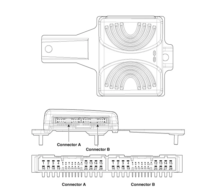
Connector Pin Information
|
No. |
Connector A |
Connector B |
|
1 |
Battery (+) |
Rear door left speaker (+) |
|
2 |
Battery (+) |
Rear door left speaker (-) |
|
3 |
Battery (+) |
Rear door right speaker (+) |
|
4 |
Battery (+) |
Rear door right speaker (-) |
|
5 |
- |
Reserved |
|
6 |
Multimedia-CAN (High) |
- |
|
7 |
Multimedia-CAN (Low) |
- |
|
8 |
ACC |
- |
|
9 |
Amplifier navigation voice (+) |
- |
|
10 |
- |
- |
|
11 |
- |
- |
|
12 |
Front door left speaker (+) |
- |
|
13 |
Front door left speaker (-) |
- |
|
14 |
Front door right speaker (+) |
- |
|
15 |
Front door left speaker (-) |
- |
|
16 |
Ground |
Subwoofer speaker 1 (+) |
|
17 |
Ground |
Subwoofer speaker 1 (-) |
|
18 |
Ground |
Subwoofer speaker 2 (+) |
|
19 |
Ground |
Subwoofer speaker 2 (-) |
|
20 |
Amplifier SPDIF (High) |
- |
|
21 |
Amplifier SPDIF (Low) |
- |
|
22 |
Amplifier SPDIF (Ground) |
- |
|
23 |
Amplifier navigation voice (-) |
- |
|
24 |
IGN1 |
- |
|
25 |
Front center speaker (+) |
- |
|
26 |
Front center speaker (-) |
- |
|
27 |
- |
- |
|
28 |
- |
- |
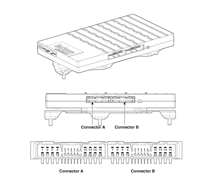
| [Harman] |
|
No. |
Connector A |
Connector B |
|
1 |
Battery (+) |
Subwoofer speaker 2 (+) |
|
2 |
Battery (+) |
Subwoofer speaker 1 (+) |
|
3 |
Battery (+) |
Front door right speaker (+) |
|
4 |
Battery (+) |
Front door left speaker (+) |
|
5 |
- |
- |
|
6 |
Multimedia-CAN (High) |
- |
|
7 |
Multimedia-CAN (Low) |
- |
|
8 |
ACC |
- |
|
9 |
Amplifier navigation voice (+) |
- |
|
10 |
- |
- |
|
11 |
- |
- |
|
12 |
- |
Rear door right speaker (+) |
|
13 |
Front door center speaker (+) |
Rear door left speaker (+) |
|
14 |
Front door right tweeter speaker (+) |
Surround right speaker (+) |
|
15 |
Front door left tweeter speaker (+) |
Surround left speaker (+) |
|
16 |
Ground |
Subwoofer speaker 2 (-) |
|
17 |
Ground |
Subwoofer speaker 1 (-) |
|
18 |
Ground |
Front door right speaker (-) |
|
19 |
Ground |
Front door left speaker (-) |
|
20 |
Amplifier SPDIF (High) |
- |
|
21 |
Amplifier SPDIF (Low) |
- |
|
22 |
Amplifier SPDIF (Ground) |
- |
|
23 |
Amplifier navigation voice (-) |
- |
|
24 |
IGN1 |
- |
|
25 |
- |
Rear door right speaker (-) |
|
26 |
Front door center speaker (-) |
Rear door left speaker (-) |
|
27 |
Front door right tweeter speaker (-) |
Surround right speaker (-) |
|
28 |
Front door left tweeter speaker (-) |
Surround left speaker (-) |
Repair procedures
| Removal |
| 1. |
Disconnect the negative (-) battery terminal. |
| 2. |
Remove the luggage side trim [RH]. (Refer to Body - "Luggage Side Trim") |
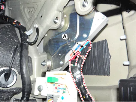
| 3. |
Disconnect the external amplifier connectors (A).
|
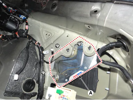
| 4. |
Remove the external amplifier (A) after loosening the mounting nuts.
|
| Installation |
| 1. |
Install the external amplifier after connecting the connectors. |
| 2. |
Install the luggage side trim [RH]. |
| 3. |
Connect the negative (-) battery terminal.
|

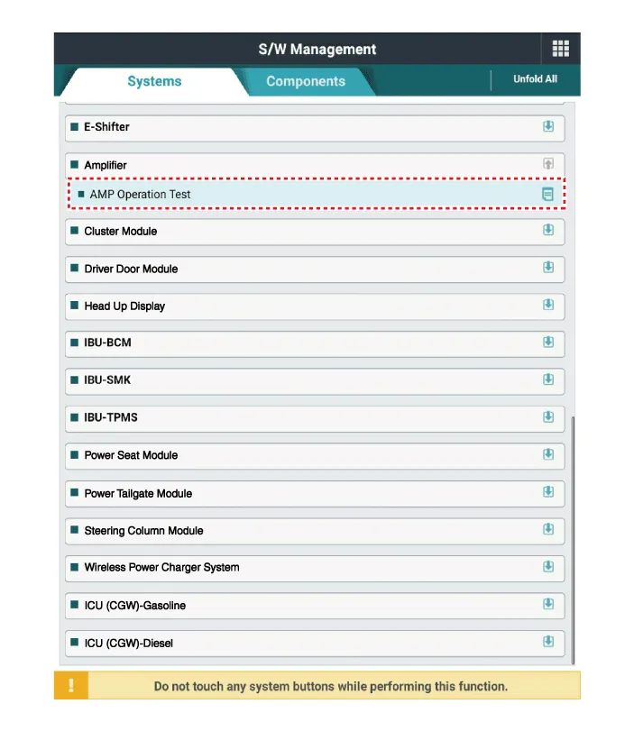
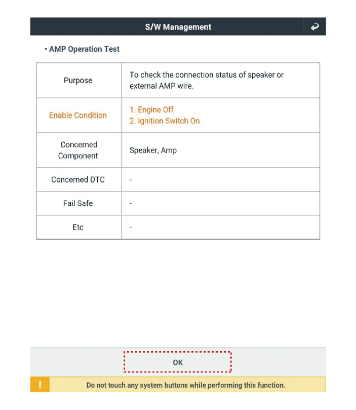
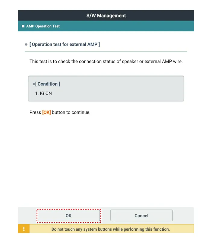
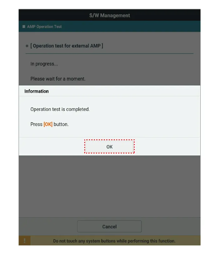
| Inspection |
|
| 1. |
In the body electrical system, failure can be quickly diagnosed by using the vehicle diagnostic system (KDS).
|
| 2. |
Select the 'Car model' and the system to be checked in order to check the vehicle with the tester. |
| 3. |
Select the 'Amplifier' to check the AVN. |
| 4. |
Select the 'Current data" menu to search the current state of the input/output data. The input/output data for the sensors corresponding to the Amplifier can be checked.
|


Other information:
Kia Stinger (CK) 2018-2023 Service Manual: Water Temperature Control Assembly
Components and components location Components 1. Water temperature control assembly 2. Engine coolant temperature sensor 3. Water outlet hose 4. Heater hose 5. Intake manifold water hose 6. Oil cooler hose Repair procedures Removal and Installation 1.Kia Stinger (CK) 2018-2023 Service Manual: Integrated Memory Seat (IMS) Unit
Components and components location Components Connector Pin Information No Connector A Connector B Connector C 1 Cushion extension motor (Front) Battery (+) Slide switch (Front) 2 Recline motor (Front) Ground Recline switch (Front) 3 Rear height motor (Up) Battery (+) FCategories
- Manuals Home
- Kia Stinger Owners Manual
- Kia Stinger Service Manual
- New on site
- Most important about car
