Kia Stinger CK: Body Electrical System / AVN System
Contents:
Components and components location
| Component Location |
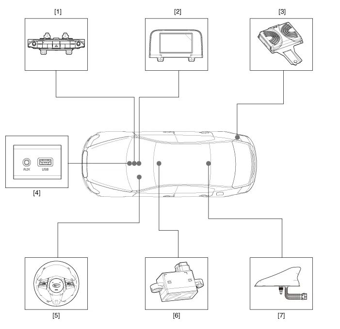
| 1 . AVN head unit 2. AVN front monitor 3. External amplifier 4. Multimedia jack |
5 . Steering wheel remote control(SWRC)
6 . Hands-free mic 7 . Roof antenna(Radio + GPS + DAB) |
Description and operation
| Description |
AVN system
The AVN system simplifies system manipulation and by unifying the vehicle information and user information displays, improves information search and operation experience.
The system is basically composed of a keyboard for the operation of combined function, LCD monitor, a head unit with Bluetooth handsfree calling, voice recognition and navigation, music amplifier and the media unit that connects with other external devices.
| 1. |
Simplification of user interface : the multimedia and car information are displayed on the monitor. |
| 2. |
Networked electronic parts : Efficient information transmission through CAN communications. |
| 3. |
Up-to-date technologies integrated :
|
System Block Diagram
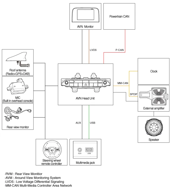
| • |
B-CAN : Body Controller Area Network |
| • |
MM-CAN : Multi-Media Controller Area Network |
Limitations Of The Navigation system
GPS Signal Reception State
As the GPS satellite frequency is received/transmitted in straight lines, reception may not work if an object is placed on or near the GPS antenna or when travelling in the following environment:
| • |
Tunnels |
| • |
Basement parking structures |
| • |
Underneath an overpass |
| • |
Roads within forested areas |
| • |
Areas near high rise buildings |
| • |
Roads within canyons |
Vehicle Position Display
| 1. |
If multipass errors occur due to reflections from buildings or related causes, the current position mark on the navigation may differ from the actual position of the vehicle. |
| 2. |
The position of the vehicle on the navigation may be different from the actual position if the vehicle is in the following location or driving condition. In this case, drive for a short period of time to automatically correct vehicle location according to map matching or GPS information. (It may take several minutes in certain cases.)
|
Route Guidance
Suitable route guidance may not occur due to search conditions or driving position.
| • |
Guidance to go straight may be given while driving on a straight road. |
| • |
Guidance may not be given after turning at an intersection. |
| • |
Proper guidance may not be given at certain intersections. |
| • |
A route guidance signaling entrance into a no entry zone may occur (No entry zone, road under construction, etc.). |
| • |
Guidance may be given to a location near the actual destination if roads to the actual destination do not exist or are too narrow. |
| • |
Wrong voice guidance may be given if the vehicle deviates from the designated route (e.g. If it turned at an intersection wherein the navigation guided to go straight.). |
| • |
The route guidance may not be provided in case of missing or incorrect map data. |
Route Re-calculation
The following phenomena may occur after conducting route recalculation.
| • |
Guidance may be given to a different position from the current position if the vehicle was turning at an intersection. |
| • |
Route recalculation may take longer when driving under high speeds. |
| • |
A route guidance signaling for a U-Turn in a No U-Turn zone may occur. |
| • |
In some cases, a route guidance may signal the driver to enter a no entry zone (No entry zone, road under construction, etc.). |
| • |
Guidance may be given to a location near the actual destination if roads to the actual destination do not exist or are too narrow. |
| • |
Wrong voice guidance may be given if the vehicle deviates from the designated route (e.g. If it turns at an intersection wherein the navigation guided to go straight.). |
AVN Head Unit ➤
Speaker ➤
AVN Front Monitor ➤
External AMP ➤
AVN Antenna ➤
AVN Remote Controller ➤
Multimedia Jack ➤
Mic
Repair procedures
| Inspection |
| 1. |
Disconnector the negative (-) battery terminal. |
| 2. |
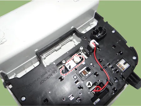
Remove the overhead console lamp. (Refer to Lighting System - "Overhead Console Lamp") |
| 3. |
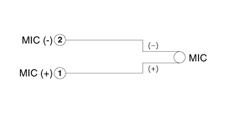
Remove the hands free mic (A) after loosening the mounting screws.
|
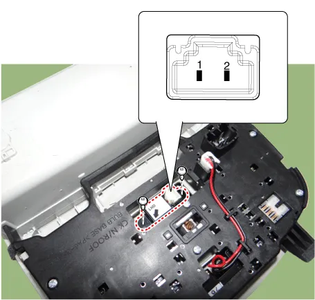
| 4. |
Check tshe continuity of between terminals.
|


Other information:
Kia Stinger (CK) 2018-2023 Service Manual: Recommended lubricants and capacities
To help achieve proper engine and powertrain performance and durability, use only lubricants of the proper quality. The correct lubricants also help promote engine efficiency that results in improved fuel economy. These lubricants and fluids are recommended for use in your vehicle. *1 : Refer to the recommended SAE viscosity numbers on the next page.Kia Stinger (CK) 2018-2023 Service Manual: Damper Clutch Control Solenoid Valve (D/C_VFS)
Specifications Specifications Item Specification Control type N/L (Normal Low) Control pressure kpa (kgf/cm², psi) 0 - 519.75 (0 - 5.3, 0 - 75.38) Current (mA) 0 - 850 Coil resistance (Ω) 5.Categories
- Manuals Home
- Kia Stinger Owners Manual
- Kia Stinger Service Manual
- New on site
- Most important about car
Contents
