
Kia Stinger CK: AVN System / AVN Remote Controller
Components and components location
| Components |
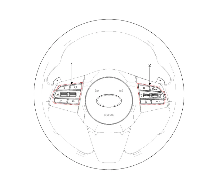
| 1. Left Remote Control Switch
(Audio + Bluetooth + Voice) |
2. Right Remote Control Switch
(Trip Computer + ACC + SCC) |
Schematic diagrams
| Circuit Diagram |
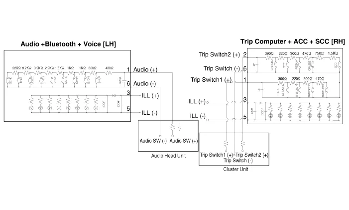
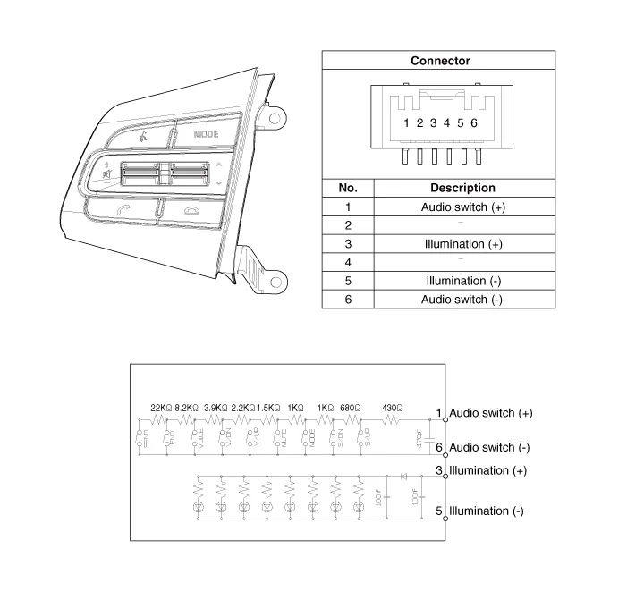
| [Audio + Bluetooth + Voice] |
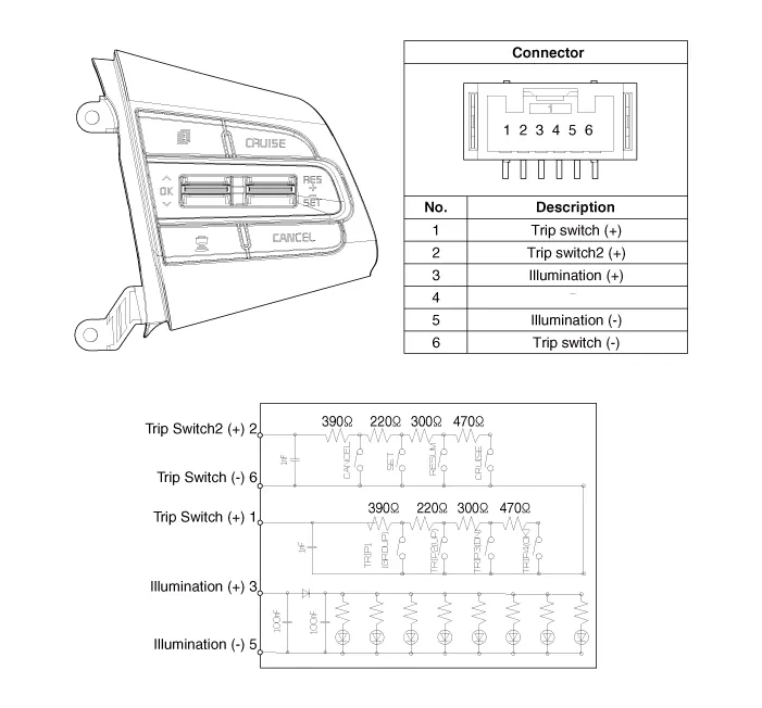
| [Trip + ACC] |

| [Trip + ACC + SCC] |
Repair procedures
| Removal |
| 1. |
Disconnect the negative (-) battery terminal. |
| 2. |
Remove the steering wheel assembly. (Refer to Steering System - "Steering Wheel") |
| 3. |
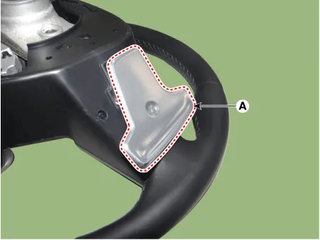
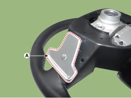
Remove the paddle shift switch (A) after loosening the mounting screws. [LH]
[RH]
|


| 4. |
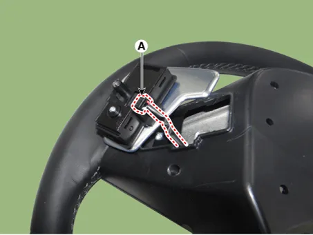
Disconnect the paddle shift switch connector (A). [LH]
[RH]
|

| 5. |
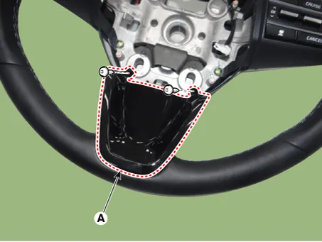
Remove the steering front cover (A) after loosening the mounting screws.
|
| 6. |
Remove the steering rear cover (A) after loosening the mounting screws.
|
| 7. |
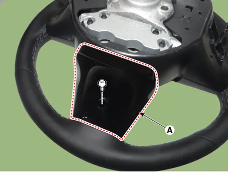
Remove the steering back cover (A) after loosening the mounting screws.
|

| 8. |
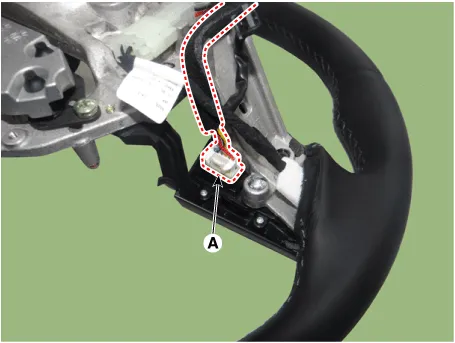
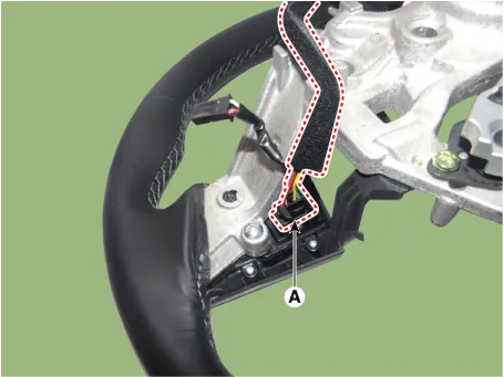
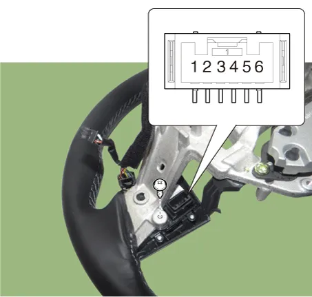
Disconnect the steering wheel remote control connector (A). [LH]
[RH]
|
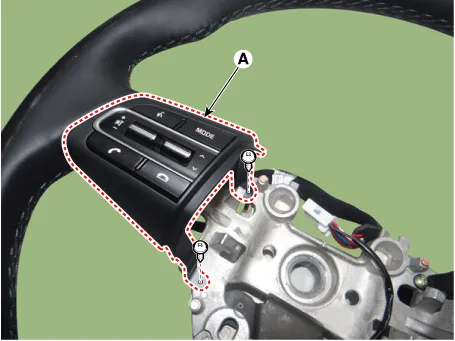
| 9. |
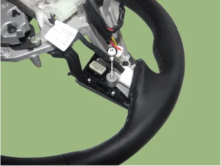
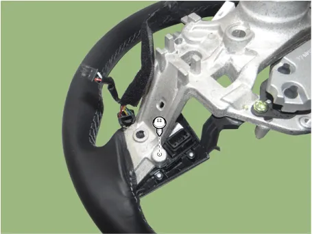
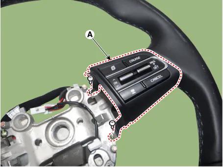
Remove the steering wheel remote control (A) after loosening the mounting screws. [LH]
[RH]
|
| Installation |
| 1. |
Install the steering wheel remote control. |
| 2. |
Connect the steering remote control connector. |
| 3. |
Install the steering back cover. |
| 4. |
Install the steering rear cover. |
| 5. |
Install the steering front cover. |
| 6. |
Connect the paddle shift switch connector. |
| 7. |
Install the paddle shift switch. |
| 8. |
Install the steering wheel assembly. |
| 9. |
Connect the negative (-) battery terminal. |
| Inspection |
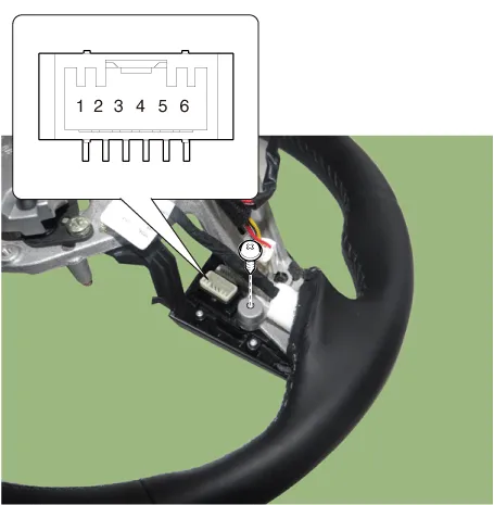
| 1. |
Check for resistance between terminals in each switch position (LH).
[LH : Audio + Bluetooth + Voice]
|
| 2. |
Check for resistance between terminals in each switch position (RH).
[RH : Trip + ACC + SCC]
|


Other information:
Kia Stinger (CK) 2018-2023 Service Manual: Front Strut Assembly
Components and components location Components 1. Shock absorber 2. Spring lower pad 3. Coil spring 4. Dust cover 5. Bumper stopper 6. Spring upper cover 7. Strut bearing 8. Insulator assembly 9. Lock nut Repair procedures Removal [2WD] 1. Remove wheel nuts, front wheel and tire (A) from hub.Components and components location Components Location 1. Roller assembly Repair procedures Replacement Put on gloves to protect your hands. • Use a plastic panel removal tool to remove interior trim pieces without marring the surface.Categories
- Manuals Home
- Kia Stinger Owners Manual
- Kia Stinger Service Manual
- New on site
- Most important about car
